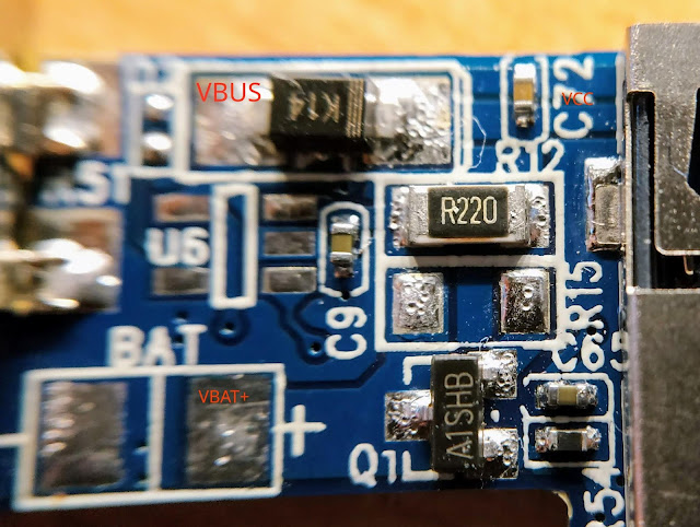
While thinking about replacing the mini usb connector to a micro one on my G600 microscope , i've seen that post from Syonyk. Damn ! No real battery charging, straight to 5v. Warning : This is not an accurate analysis, it may contain errors or missing /misunderstood parts. Let's have a look. The partially reverse engineered/ contains error schematic /picture is as follows : The equivalent schematic is ( incomplete/may contain error ) : So indeed, VBUS (5v) is connected directly to VBAT through just a schottky (K14) and R12. On the other hand, the BMS circuit is tuned very low and will stop the charge at exactly 4.2 v. My battery is still healthy and only slightly puffy :) Let's use a real charging circuit and remove component so that VBUS is completely isolated from VBAT. Remove K14, the P-Mosfet (Q1) and R54 so that they are really isolated and there is no resistor between VBUS and ground (R54). I also removed a very small ...
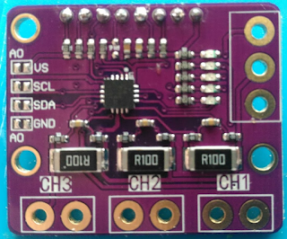
Continuing my "smart" battery charger, i've finally received the INA3221 module. It is the purple one you can find on ebay for ~ 5 bucks I soldered a couple of pins to be able to connect it so that i could test it and something immediately caught my attention. It is supposed to be a high side current/voltage sensor, typically in a setup like that : So you can measure the voltage supplied to the load, and the current going through it. Now, let's have a look at the module, look at the top of the following pic, where the sense connectors are. CH3/GND/CH2/GND/CH1/GND ? Wait ? What ? Yes, all the IN- pins are connected to ground, so it is a bottom current only sensor. Additionally, the - side of the shunts are ALSO connected to the ground, no only the connectors. The actual layout is like that : That raises two problems : The voltage is meaningless as we are only measuring Current x ShuntValue, not the supply volt...
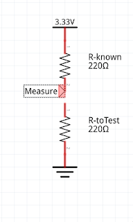
I was always fascinated by the so call "transistor testers" that identify and report pin out, features of pretty much whatever you throw at it. They are based on Atmel 328p chip, the same as arduino nano. So why not do the same thing with a STM32/Bluepill ? The STM32 is faster, has a better ADC accuracy, more memory, can do float etc... and is not more expensive. Warning : I'm doing this for fun & to learn, it might contain error & plain misunderstanding So, i watched a couple of video on the general principle on how they work. This is not a "port" but a rewrite from ~ scratch. When something is weird, i check what the original one does for comparison. Measuring resistance So first thing first : Resistance & Capacitance. These 2 will unlock the other ones. So how do we measure resistance ? What we do is a resistor divider with a know resistance value: Measure = Vcc*(RtoTest/(RtoTest+Rknown)) As far as the ADC goes, it means ADC=...

Comments
Post a Comment