Posts

Showing posts from September, 2021

More esp32c3/jtag

Image
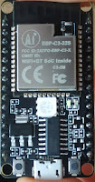
 Using the embedded usb/jtag link with the esp32c3 was really unstable.  Once in a blue moon it was usable  (tried on 2 modules). So let's consume more pins and have something that works better : 1- Step 1: Be sure you have a recent esptool (  https://github.com/espressif/esptool ) 2- Step 2: We'll burn the JTAG_SEL efuse so that the jtag is connected to either the internal usb stuff or the IO4...IO7 pins depending on the state of IO10 at reset espefuse.py  burn_efuse JTAG_SEL_ENABLE 3- Step3 : Hardwire IO10 to ground, that way we force the jtag on the external pins 4- Step 4: Connect your favorite Jtag probe , the mapping is as follows :     TDO IO07     TCK IO06     TDI  IO05    TMS IO04 /!\ Important: make sure you have some *not* brain dead code programmed in. If the chip deep crashes right at start, even the  jtag will not work properly. The default way to set it up ( from what i understood) is as follows : * you program the chip using idf.py flash or similar * you debug w

Playing with another RiscV chip : ESP32C3 , Jtag adventures

Image
While still having fun with the GD32FV103, which are very good low end MCU,   I also bought a few cheap esp32c3 boards on aliexpress, like those ones (esp32c3 32S) Installed everything, built hello world, all is fine. Now time to have a real debugger. openocd installed, gdb ready, let's go. According to the nice documentation, the jtag/serial-to-usb bridge is included in the chip, no need for a FTDI or similar. Great ! Problem is, when connecting the board to my linux, it only detects a CH340 serial to usb chip, which is indeed present (it's the big black rectangle at the bottom). Ok, no problem, we'll use directly TDI/TDO/TMS/TCK aka GPIO 5/7/4/6 with a ftdi. Does not work either .... Ok it seems that the jtag, by default , is routed to the internal USB component which is not connected. Two options here from what i understood : * Blowing efuse to change the connection from internal usb to external pins. Should work, but we'll lose 4 gpios, that' s a bit too much. W

Inductance tester , continued

 I tried previously to measure the inductance of a coil using the same method as for capacitors : take 2 points in the charge/discharge curve and compute the L value After a pulse on the coil, the voltage across it is (1-exp(-t*R/L)), so if we have t, R and 2 points we can compute L. The problem with inductance is the curve is very very small, like ~ 1us, way too fast for the ADC, and using very small R will give high current. Recently i saw a youtube video from DiodeGoneWild ,  he showed his own inductance meter It's 100% pure analog, no MCU. How does it work ? It sends GND/VCC squares to the coil do trigger charges/discharges. A schmidt trigger creates a nice square when coil voltage is between 1/3 and 2/3 vcc. The duration of the square gives the inductance. Measuring a small-ish duration is not easy to do with analog circuits so that's how it does it : since a PWM is charging/discharging the coil and generates squares, the output squares are integrated though a 2nd order lo

T7 component tester teardown

Image
 I bought this unit for cheap on amazon. Didnt really play with it until i wanted to check something on a vanilla NPN transistor.  It gave a hFE of 426.  Really ? That's a bit high, i checked with my own tester and the datasheet, they both gave around 250. Okay, time to open it up : The MCU is an Atmel 324 with a 16 Mhz quartz There is a second tiny MCU a STC 8G1K08 (??) The AL088 is maybe a step up converter circuit The 7DA5 is probably a lithium charging circuit V05 are TVS Build quality is fine, just a bit of flux i cleaned up There is also a "431" on the top right, probably a TL431 voltage reference for the ADC.