Posts

Showing posts from January, 2019

DSO Shell - Rewired rotary encoder + buttons

Image
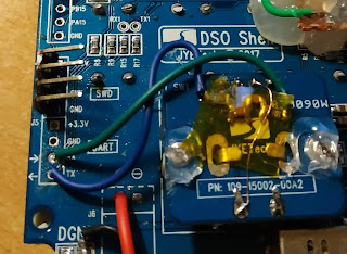
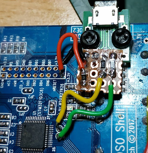
So, as seen previously, the screen is conflicting with the rotary encoder making it very inaccurate and unresponsive. We have freed the RX/TX pins , so we can use them as left/right for the rotary encoder While we are at it, let's add some hardware debouncing to reduce the noise on the interrupt lines of left/right. Again, it does not conflict with the screen any longer, so we can add caps to the lines. I cut the 1 & 2pins below the rotary encoder (the 2 left side on the pic), that disconnects PB0 & PB1. The regular buttons are now managed by a FreeRTOS task that lazily poll them and do software debouncing. Since we are using RX/TX pins, we have the rotary encoder connected to port A. No need to block the EXT irq when updating the screen (port B) => no missed transitions. The interrupt is pretty fast, just a lockup table search. The buttons are a two layers software debouncer, so no interrupt there either. First an integrator debouncer to filte

DSO Shell: Micro USB mod

Image
This is a very simple modification, you just need 3 resistors and a micro usb connector breakout board. And now, we have USB live, serial  output  for the moment, exactly like a bluepill. That frees the RX/TX pins, we have something much better instead of basic serial. Might be a good idea to use them for the rotary encoder at a later point. The mod (with the usual craftmanship), it is really simple to do. I superglued 2 acrylic nuts to the board, so that i can screw the micro usb on them. It needs more mechanical strength (yes, it will be hotglue) The schematic :

DSO Shell , weird pin usage & rotary encoder

Buttons The DSO Shell has a ILI9341/ST7789 LCD screen driver connected in parallel, which makes it very fast to refresh the screen. The 8 Bits LCD data bus is using PB0..PB7. BUT , the PB0..PB7 are also used to control the buttons & rotary encoder, as inputs this time. The mapping is as follows : PB0/1 => rotary encoder left/right PB3  => rotary encoder button PB4 => Voltage button PB5=> Time PB6=> Trigger PB7=> Ok It means PBx are constantly switching between input and output modes and that you cant do both at the same time. It also means you cannot have hardware debouncing on the button as it would soften also the LCD signals. That's weird, there are plenty of available pins. Some of them  ( PB13, 14, 15) are even routed to the "Spare IO header" The problem is that each time you do a LCD access, the code blocks PBx interrupts & re-enables them afterward It means that during long drawing, you'll lose some interrupts a

DSO 150+STM32Duino+black magic = lot of fun

Image
I have bought a second DSO 150, a cheap STM32 based oscilloscope. They are low frequency, single channel, but cheap and easy to modify. Mine is now battery powered, with a usb plug to charge it (the stuff is 3D printed, model is available on thingiverse  ) It appears that they are pretty close hardware-wise to our beloved bluepill . Solder the SWD pins, connect our custom blackmagic and we are ready to go. First step, flash a random bluepill bootloader so the board boots as a bluepill. Works. Second step: the screen. Looking at the  Open DSO 150 project  gives a lot of information regarding the hardware setup. The screen pinout is a bit unusual :    Read PA6    Write PC15    RS         PC14    CS         PC13    Reset PB9 Data is sent using the 8 lower bits of Port B. So first step is to patch the  8 bits ILI9341 lib   to use the right pins. .... and it still does not work After digging a bit and probing the pins, conveniently placed on a te

Digitally controller power supply, continued

Image
I'm posting the schematic of the i2c controlled power supply here, in case somebody is looking into a similar project. It works, output is stable, i2c control works fine BUT That circuit is way too sensitive to noise. In particular, when the spi clock is refreshing the screen, it induces nastly glitches on the output (like ~ 1v glitches) You dont even need to connect a screen, just put a wire on SPI CLK as an antenna. The layout needs to be re-done to avoid long wires jumping from board to board. The principle is sound though