Posts

Showing posts from May, 2017

Arduino + cmake + netbeans = success !

The Arduino IDE is very easy to use, but it lacks features. Fortunately, there is a very nice project to use cmake with the arduino very easily. I've used the following fork   on github In particular, it can sort of automatically import most of the config directly from the the .ino file ( most is the critical part) First some pits &traps  : Library naming The library names must strictly follow the arduino naming rule. i.e. it must contain MYMODULE/MYMODULE.h. Layout  like     MYMODULE-0.1/MYMODULE.h or     MYMODULE_library/MYMODULE.h will fail. Create symlinks as needed. Includes The libs to include are autoprobed from the #include in the ino file. The parser is picky, make sure you dont have comments / space/ tabs AFTER the include. This will fail #include <foo.h> // some comment Nano For my nano i had to add the following set set(ARDUINO_CPUMENU .menu.cpu.${ARDUINO_CPU}) Libs Simple libs are automatically probed and built Complicat
Safer - 18650Battery tester

Image
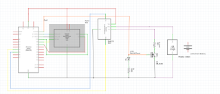
That one is a classic : How to test salvaged 18650 batteries and their capacity. My implementation is derived from a very classic one as found on instructables , with 2 differences : I'm using an INA219 to measure the current. That way i can use different load resistors to speed up the test, no need to calibrate anything. There is a TP4056+DW01 between the circuit and the battery. The TP4056 role is to add security (short circuit, too deep discharge etc...) and later on to automatically re-charge the battery at the end of the test.  I dont have P-Mosfet available to do it at the moment, but is is easy enough to do. /!\ the TP4056 disconnect the negative when it enters in security mode /!\ When in security mode, you have to connect the usb charger to reset the circuit /!\ To be on the safe side, the battery discharge will stop at 3.2 Volt So at the moment, due to lack of P mosfet, you have to physically unplug the arduino and plug the TP4056 to load the batter

Arduino power supply : Completed schematics + pics + code

Image
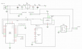
Update : There is an updated version with better current limiting + better software  here Here is the ~ correct schematic Some pictures (i know it's ugly) The finished box (outside) Internals And the source code (sorry, can't attach it) /** * Simple power supply monitored by arduino * - We have an INA219 monitoring voltage and current * - Basic relay (with protection diode) disconnecting output when active * - Nokia 5110 screen printing out voltage and amps * * Gettings the current limit is a bit tricky as it is done in anolog world through a resistor */ #include <Wire.h> #include <Adafruit_INA219.h> // You will need to download this library #include "U8glib.h" U8GLIB_PCD8544 u8g(12, 11, 9, 10, 8); // SPI Com: SCK = 13, MOSI = 11, CS = 10, A0 = 9, Reset = 8 Adafruit_INA219 sensor219; // Declare and instance of INA219 float currentBias=300./1000.; // to correct current bias bool connected=false; // is the relay

Arduino Powered power supply : Part 2, Arduino + modules (in progress)

Image
The arduino will just be in charge of displaying current/voltage and control. What do we need ? (I've put the link to the ones i've used, any similar will do) : A screen  : A Nokia 5110 style screen is fine A voltage/current   meter : Small module based on INA219  A relay  + tact switch  : To disconnect/connect outputs. It starts disconnected. A fan: Using one i had lying around  An arduino micro (any arduino will do, as long as its IOs are 5v) The first tests showed that all that was drawing a little bit too much current, so a small PCB was added with a 7805 to dispatch power to all the modules and  i2c also for future expansion if needed.. The schematic looks like that (it is work in progress, some parts are missing or incorrect) The relay module has the protection diode built-in and is wired to be off at reset. The fan is PWM controlled, it connects directly to the 12V, the PWM is connected to the arduino. -- To be completed --

Arduino : Pot schematics

Image
As a follow up to  Arduino power supply, part 1 , the schematic for the pots below A note of warning, the 3870 chip hates to have its voltage feedback loop open In other words, if you dont connect something on the right pot, you might fry it (personal experience) The 1M resistor on the max current is to increase the gain. As a result, the max current will be less (4Amps, the original 20A value was dummy anyway), but the minimum current is also slightly less (~ 100 mA).

LTC3780+Arduino powered power supply

First part of Arduino powered power supply Link