Posts

Showing posts from September, 2017

Fixing the INA3221

Image
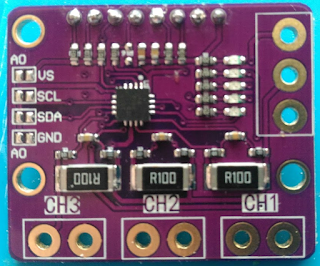
It 's not too complicated to change the board we have seen  previously . You 'll need to cut some tracks, i did it with a dremel and i'm not very handy, so you'll do better. Red =Cut tracks Blue = Add wire 1- You'll need to separate the bottom connector from the ground, cut the 3 connectors BOTH SIDES. 2- Remove the small red area below the middle resistor to isolate each channels from each other Last, connect right side of each connector to the now isolated pad. Mine looks like this after the operation (ugly i know): Be wary of the small track on the left connector that leads to the left side of channel3 resistor. I cut it while isolating the right pad. Now it works, we can go back to the charger.

INA3221, weird wiring

Image
Continuing my "smart" battery charger, i've finally received the INA3221 module. It is the purple one you can find on ebay for ~ 5 bucks I soldered a couple of pins to be able to connect it so that i could test it and something immediately caught my attention. It is supposed to be a high side current/voltage sensor, typically in a setup like that : So you can measure the voltage supplied to the load, and the current going through it. Now, let's have a look at the module, look at the top of the following pic, where the sense connectors are. CH3/GND/CH2/GND/CH1/GND ? Wait ? What ? Yes, all the IN- pins are connected to ground, so it is a bottom current only sensor. Additionally, the - side of the shunts are ALSO connected to the ground, no only the connectors. The actual layout is like that : That raises two problems :  The voltage is meaningless as we are only measuring Current x ShuntValue, not the supply volt

Simple TP5100 based charger

Image
Using a TP5100, let's do a 2S battery charger. The requirements are : Usb powered, so ~ 10 W max with a 2.1A charger Using cheap ebay voltage boost converter, ~ 10 W max too That's why limiting the charge current to 1A is important. With the default 2A charging current, we would exceed both the Usb charger and the boost converter specs. What's needed  :   MicroUsb breaking board .   Boost converter .   TP5100 .  3 small leds : PowerOn, Charging, ChargeDone.  A 4kOhm resistor for the powerOn led, connected directly to the usb 5v. It is so simple, no need for schematics. The end result : As usual, crap design & workmanship. Important : It is much better to wire external leds rather than using the built-in dual led. When nothing is connected, the "Charge done" led is on, the "Charging" led is blinking very quickly. It is hard to see on the default very small dual led. Update 1: It was working fine with mostly c

First look at TP5100

Image
The TP5100 is the successor to the ubiquitous TP4056 It is slightly more expensive, but with some interesting features : 4.2 or 8.4 (2S) battery charge Buck converter instead of linear, dont heat much Pin-out for external led display No battery protection on the  board Here is a pic of the small board you can easily find on eBay : To switch to 2S mode, you have to join the 2 "SET" marks on the silk (bottom left). It is a buck regulator, so in 1S mode you have to supply >= 4.5 v, in 2S mode >=9v. By default, the chip is configured in 2A charging mode, which is a bit too much for my taste. If we look at the  datasheet  (in Chinese), we can see that 2A = 0.05 ohm setup resistor. That's consistent with the two 0.1 Ohm in parallel on the top left. Let's remove one : Now we are at 1A charging current according to the datasheet, and confirmed by my power supply. On the right side of the board, you can see 3 holes. It i