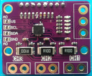
INA3221, weird wiring
Continuing my "smart" battery charger, i've finally received the INA3221 module.
It is the purple one you can find on ebay for ~ 5 bucks
I soldered a couple of pins to be able to connect it so that i could test it and something immediately caught my attention.
It is supposed to be a high side current/voltage sensor, typically in a setup like that :
So you can measure the voltage supplied to the load, and the current going through it.
Now, let's have a look at the module, look at the top of the following pic, where the sense connectors are.
CH3/GND/CH2/GND/CH1/GND ? Wait ? What ?
Yes, all the IN- pins are connected to ground, so it is a bottom current only sensor.
Additionally, the - side of the shunts are ALSO connected to the ground, no only the connectors.
The actual layout is like that :
That raises two problems :
- The voltage is meaningless as we are only measuring Current x ShuntValue, not the supply voltage
- The IN- pin is hardwired to ground. It is a problem in our case, since the TP4056 protection module disconnects the - pins. If we use that sensor, we'll bypass the protection circuit.
So time to take the dremel out and butcher that thing.
Be warned, i'm not very good at that kind of stuff.
Follow up : "Fixing it"


That is a bit weird. I have 2 such modules and they seem to be wired high side to a common Vin:
ReplyDeleteVin-- 100 mOhm -- ChannelX
I bought a new one from a separate source, i'll check if it is different
ReplyDeleteThere may be a misunderstanding here, about the schematic. From your photos it shows you actually supposed to connect the load between the GND and CH1, and battery between PWR(+) and GND. According to data sheet, I'm quite sure the IN- should actually be connected on the supply side of the shunt resistor, and IN+ to the load-side - which probably confuses some people.
ReplyDelete