Posts

Showing posts with the label COMPONENTTESTER

Inductance tester , continued

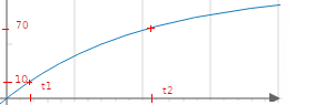
 I tried previously to measure the inductance of a coil using the same method as for capacitors : take 2 points in the charge/discharge curve and compute the L value After a pulse on the coil, the voltage across it is (1-exp(-t*R/L)), so if we have t, R and 2 points we can compute L. The problem with inductance is the curve is very very small, like ~ 1us, way too fast for the ADC, and using very small R will give high current. Recently i saw a youtube video from DiodeGoneWild ,  he showed his own inductance meter It's 100% pure analog, no MCU. How does it work ? It sends GND/VCC squares to the coil do trigger charges/discharges. A schmidt trigger creates a nice square when coil voltage is between 1/3 and 2/3 vcc. The duration of the square gives the inductance. Measuring a small-ish duration is not easy to do with analog circuits so that's how it does it : since a PWM is charging/discharging the coil and generates squares, the output squares are integrated though a 2nd order l...

T7 component tester teardown

Image
 I bought this unit for cheap on amazon. Didnt really play with it until i wanted to check something on a vanilla NPN transistor.  It gave a hFE of 426.  Really ? That's a bit high, i checked with my own tester and the datasheet, they both gave around 250. Okay, time to open it up : The MCU is an Atmel 324 with a 16 Mhz quartz There is a second tiny MCU a STC 8G1K08 (??) The AL088 is maybe a step up converter circuit The 7DA5 is probably a lithium charging circuit V05 are TVS Build quality is fine, just a bit of flux i cleaned up There is also a "431" on the top right, probably a TL431 voltage reference for the ADC.

STM32 Based component tester

 No recent news recently on the  STM32 based component tester So a quick summary : * Supports STM32F103/GD32F103 (borderline in term of flash size)/GD32F303 * Resistors * Capacitors down to ~ 10 pf * Diodes (with VThr < 3 v) * NPN & PNP transistors (hFE, Diode voltage) * N &  P Mosfets (Vgsthresh, RdsOn, Diode) The only ones i cannot figure out are coils.

Stroboscopic ADC- follow up, VERY LOW capacitors

 I've spent a lot of times on this due to a silly bug. The sillier it is , the harder it is to find out. Now, it works fine. For reference, we sample a cyclic waveform, repeating every N cycles by sampling it every N+x cycles. That gives an apparent sampling period of x. In our case, for the STM32/GD32, the higher sampling frequency is 72M/PWM divider (1 or 2)  (96M for the GD32). That gives an equivalent smallest sampling period  of 14nS (10 nS for GD32), compared to the 500 ns maximum using the "regular" method. Let's inject that into our capacitor measurement stuff and check the results : C Me M328 0 N/A N/A 3 2,54 N/A 10 9,65 N/A 20 19,4 N/A 47 47,6 52 56 55,6 60 68 70 75 100 96,8 101 220 231 232 310 323 330 The first column is the value written on the tin The second column is the value measured by our tester The 3rd column is the value measured by a M328 transistor tester (cheap chinese version) Not too bad, and we can go down to ~ 2pF. The main drawback of that ...

Measuring low level cap/inductance and stroboscopic mode

The scheme we have used so far to measure capacitor is to generate a square pulse and capture the voltage waveform.   For reference, the STM32/GD32 MCUs have very decent 12 bits ADC that can go down to ~ 0.5/1us sampling frequency. For capacitors, the time constant of the waveform is proportional to Resistor*Capacitance, so if we use the bigger resistance (470k) we can have a few points even with very small caps. NB: The waveform is V*(1-exp(t/RC)), so with 2 known points we can calculate R*C. Since R is known , C can be computed. It gets problematic with inductance.  The time constant is proportional to L/R, so with the smallest R (470 Ohm) and 100 uH inductance that leads to time constant  in the order of ~ 100E-6/470= 200 ns, which is way too small compared to the ~0.5/1 us resolution of the ADC. Additionally, we need at least something like 5 points to have a valid guesstimate. So we are out by a factor of 10. I've been scratching my head on that one for some ti...

Component tester : 2nd prototype, getting there

Image
The 2nd prototype is about to be ready, still need to debug it a bit. The aim is to end up with a PCB at some point. The schematic as it is today (yes, i'm a kicad complete noob): About 60% of it is just some helper components to have the MCU up and running. Both STM32F103 and GD32F103 work The LMV324 is there  to avoid error : The ADC is pulling ~ 1uA when sampling which could skew results for low value capacitor/high value resistor. If you really need to remove it, you can bypass it completely. As of today the following works with prototype 1 : Capacitor Resistor NPN/PNP transistor N & P mosfet Diodes Accuracy is ~ 2%

Capacitor, updated

Image
So here is the new method to measure capacitor : First, identify if it is a low cap, medium cap or high cap. If it is medium cap we select the right range and capture 512 samples of the charging voltage. When we have those 512 points , we take 2 points at ~ 10% and ~ 70% to compute the capacitor value                                     C=   (t2-t1)/Rcharge*Ln((4095.-V1)/(4095.-V2)); If it is a low cap, we take the 2nd point at ~ 90% to have a better accuracy (it takes 2.3x more time to go to 90% compared to 70%) If it is a high cap, we do the same thing but poll the ADC instead of doing dma capture (it takes a long time, the error introduced by polling is very small). But how do we select the right method ? First do a high speed dma capture. If we are under 10% of the 512 samples to reach 70% of the charge, it means it is a low cap. If not, do a slow speed dma captur...

STM32F1 ADC Weirdness

That one had me scratching my head for a while. Depending on the speed of the ADC, there is a small current being eaten by the ADC itself, in the range of 0.5uA to 3 uA. Why is that a problem ? 1- It happens even if the ADC is not sampling, which is really weird. When using high current ( a few mA), it is not visible at all. 2- But when using a large resistor (i.e. 300kOhm), that small current is enough to cause a voltage drop of sever tenth of a volt, ruining the measures. For reference, with the 300 kOhm (or 2x300 kOhm) the current is ~ 10 uA (or 5uA) , so a ADC leaking 2uA is not neglectable at all. At the fastest speed (worse effect), it causes the capacitor to cap at 3v (or 2.5v) rather than ~3.3v which ruins the estimation. To confirm, i cut the ADC wire and voila, back to ~ 3.3 v The estimation of the current is as follows (the different rates/scales of the ADC clock can yield different result for the same sampling period) : Samp period (us) i (ua) 2.16666666...

Component tester : Capacitor

The charge curve of a capacitor is Vc=Vcc*(1-exp(-t/RC)) The idea is to charge the capacitor up to ~ 70% and look how much time it took The formula is then inverted to  : C=   -t/R*(ln(1-ADC/4095) The problem is C can go from 1pF to 400 uF, that's a 400000000 factor So what we will do is charge up to 10% using the 20 k resistor and lookup how much time it took Depending on the result, we'll select the right resistance and do it again.  That initial sampling does not need to be accurate, it's just to select the right resistor. The idea is we aim at a charge time of ~ 200 ms so the errors are neglectable. For mid values and high values capacitor that works fine (C above ~200 pF or so) We poll the ADC with slow sampling period until we get over ~ 70% and compute the capacitance value from there. It does not need to be exactly 70% since we have the matching ADC value. The limit is here is the sampling period is a few us, which is fine if R*C is big comp...

Component tester with STM32 : Part 1 ADC, Resistor

Image
I was always  fascinated by the so call "transistor testers" that identify and report pin out, features of pretty much whatever you throw at it. They are based on Atmel 328p chip, the same as arduino nano. So why not do the same thing with a STM32/Bluepill ? The STM32 is faster, has a better ADC accuracy, more memory, can do float etc... and is not more expensive. Warning : I'm doing this for fun & to learn, it might contain error & plain misunderstanding So, i watched a couple of video on the general principle on how they work. This is not a "port" but a rewrite from ~ scratch. When something is weird, i check what the original one does for comparison. Measuring resistance So first thing first :  Resistance & Capacitance. These 2 will unlock the other ones. So how do we measure resistance ? What we do is a resistor divider with a know resistance value: Measure = Vcc*(RtoTest/(RtoTest+Rknown)) As far as the ADC goes, it means ADC=...