Posts

Showing posts from December, 2019

ESP32 : FTDI 2232 HL + Gdb setup

Image
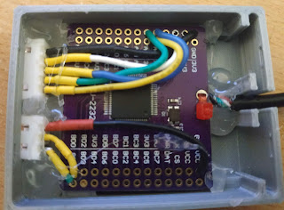
FTDI 2232 I've redone the wiring of the FTDI so that it's a bit cleaner, with shorter wires The 3 pins connector is for serial. Why bother ? there is already one on the ESP32 ? Because each time you reset /stop the chip, the serial usb device disappears and you have to restart the serial console The one on the FTDI will stay present, so you won't loose the connection The pinout is  on the left connector: ESP32 FTDI SIGNAL GND - GND GND 13     - AD0 TCK 12     - AD1 TDI 14     - AD3 TMS 15     - AD2 TDO and on the right connector ESP32 FTDI SIGNAL GND - GND RXD - BD0  TXD - BD1  GDB I played a bit with the normal gdb+openOcd setup, it does not work really well. On the over hand, PlatformIO works without a hitch, so the hardware is fine. After looking on the tubes, I ended up doing something a bit convoluted : Extract  a .bin from the elf using esptool  (arduino-cmake-stm32 in esp32 mode does that) Extract a .debug from the elf using

ESP32 : Preparation step 1, Jtag debugger, FTDI 2232

Image
Arduino are fun, but they have 2 major problems : All is in the IDE, and the arduino IDE is good for beginners, not for "normal" use Lack of debugging capabilities The arduino-cmake-stm32 deals with the first issue, for both Arm cores and Atmel cores. The stm32 has SWD capabilities, so at least when using stm32, you can debug (plus they are much more powerful than the Atmel Arduino boards) Stm32 + arduino-cmake-stm32+ your favorite IDE+ ST LINK/Black Magic = :) Now let's have a look a the ESP32 from espressif. They are a bit more expensive, but they contain a LOT of hardware features (ADC/DAC/Bluetooth/Wifi/....) They do support the arduino API,  back to square 1. First thing first, debugging. The ESP32s do not support SWD interface, but they do support the jtag interface. You can uses a FTTDI 2232 H board , available for ~ 10$ on ebay to do jtag/usb conversion. I bought that one a few months back :  Ebay link  (it is not sponsored

NTC : And more calibration

Let's really calibrate our NTC, for reference it is sold as a  3950 NTC, 100k at 25 °C The formula is still   Beta= TxTref x ln (Rref/R) / (T-Tref) with Tref: Reference temperature, normally 25°C         Ref : Resistance value at Tref Which can be transformed to ln(Ref/R)=B*(T-Tref)/(T*TRef) or ln(Ref)=B*(T-TRef)/(T*TRef)+ln(R) The left part is a constant, so if we have 2 values, T1/R1 and T2/R2, they 'll have the same ln(Ref) The two equal parts are B*(T1-TRef)/(T1*Tref)+ln(R1)=B*(T2-TRef)/(T2*Tref)+ln(R2) that can be expressed as B=ln(R1/R2)*(T1*T2)/(T2-T1) NB: All temperature are in Kelvin in the formulas, so you have to add 273.15 We just need two points to compute beta. Let's put the whole thing in the fridge to have both ambient and ~ 5 degrees. We end up with our two points : T=21°C, R=112k and T=5°, R=217K, convert to kelvin, put that in your favorite spreadsheet to get => B=-3382 Now we have beta, we can compute Ref ln(Ref)=B*(

Anycubic i3 mega+ SKR 1.3

Image
What is the status so far ? Works perfectly, with a couple of configuration gotcha's I've created a github project with my Marlin 2.0 configuration : https://github.com/mean00/SKR_1.3_OnAnycubic_I3_MEGA i'm using the following setup : * No sensor (did not manage to have the cheap clone working) * Full Graphique 12864 LCD Smart Display Controller (cheap and works out of the box) * 5 x TMC2130

MT3608 with wrong resistor value

Image
I bought a few boost converters on ebay, they are based on MT3608, up to 30V, ~ 500 mA max which is fine for a lot of applications. Of course they are cheap. But they dont work, Vout~=Vin whatever the potentiometer says. Let's see why They do look like this : The variable resistor is "102" i.e. 1kOhm, the fixed resistor is 222= 2.2k The circuit works like this  Vout    1k variable ==> FB    2.2k Gnd Vout is adjusted so that FB is 0.6V Let's write down the general equation for that circuit FB=0.6=Vout*(2.2k+alphaR)/(2.2l+R), with : * R the value of the variable resistor (1K) here * Alpha the coefficient of the variable resistor between 0 and 1 The module should be able to go up to 30V, with alpha=0 0.6=30*(2.2)/(2.2+R) => R=107 kOhm Ooops, the variable resistor is 1k (102) instead of 100k (104),  it cannot work with the value Two options : Replace the variable resistor with the proper value i.e. 100kOhm Or hardwire the value we

NTC continued, it needs to be calibrated

So far, the NTC thermometer was working fine at about 20 C But i noticed that when the actual temperature was going down (it is winter after all), the reported temperature not so much So time to use high quality testing equipment: Put the whole thing in the fridge A normal fridge is about 4  or 5 degrees C Reported temp : 9 Degrees. Something is wrong there. Let's compute the actual beta of the NTC. Put a voltmeter in Ohm mode at the NTC in the fridge for a bit at 5 degrees : Result= 218 kOhm Beta = T*Tref*ln(Rref/R)/(T-Tref) with T=5+K  (K=273.15) Tref=25+K Rref=100kOhm R=218kOhm => Beta= -3230 So not really -3950 With the actual beta value,  it works much better