Posts

Showing posts with the label CHEAPHANDHELD

CH32F103/FNIRSI: Success!

Image
 Still some minor tweaks to apply, but it works 

CH32F103/DSO150/FINRSI coupling selection difference

 There is another difference with the original DSO : CPLSEL pin With the original DSO, the CPLSEL (PA5) is an analog pin which gives the info about the selected coupling. When reading it with the ADC, you get : -   0 => GND -  ~ 2024=> DC -  4095 => AC (not necessarily the right values, but the principle stands). The FINRSI clone is different. It uses the CPLSEL pin *AND * another pin the "KEY" pin (PB12). That pin  was used a long time ago but is no longer needed as the threshold detection is done using the ADC watchdog Both CPLSEL and KEY are pull up GND:    CPLSEL=1   KEY=1 AC:    CPLSEL= 1    KEY= 0 DC   CPLSEL=0   Key=1 So it wastes one pin, but makes the reading much much more simple. NB: The CH32 only has one ADC, that may explain.

lnDSO150 : DFU ready for STM32F103 and GD32F303

Software is ready and works fine if you have 128 kB of flash or more. Sofwtare update over usb at last ! A lnDSO150 release will be coming soon, as soon as the CH32 chip works.

CH32F103 based DSO150 (FNIRSI clone)

 So i finally bought one to make sure lnDSO150 does run on it. First feedback : - As expected the main diff is the chip is a CH32F103 instead of a STM32F103. I added support for the CH32F103 on the blackmagic probe, so it should not be an issue to reprogram it. - The main board seems almost identical to the original one. R12 and R13 are missing which might indicate the buttons are not wired the exact same way, which would explain the problem report about pressing "OK" not working. - Some components are missing , mostly the trigger comparator stuff which is a leftover of older software. - The analog board is similar but more compact and using 100% SMD components. The FNIRSI software is not bad, looks pretty, very close to the original one in look & feel. But it feels a bit slow, we'll see how lnDSO150 performs on the CH32F103 More on that soon. Edit : Indeed, the "OK" and "Trigger" button are connected to PA11 / PA12 instead of PB6/PB7 Edit 2: There...

Using Analog stick

Image
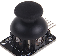
  Still planning to pimping the cheap handheld console, so i bought a few of these cheap analog sticks. They are pretty simple, just 2 rotary potentiometers, converting the angle to a voltage divider. The voltage is VCC/2*(1+sin(Angle)) With angle from -90 degree to + 90 degree  A simple lookup table will easily invert that, to get the angle from the voltage.

Cheap handheld, a closer look at the screen

Image
It seems the screen is a fairly standard 16 bits parallel interface driven by ILI9341 style controller. The following annotated picture contains  a lot of guesswork, but this is how it seems to be connected : The main issue is finding how to switch it to 8 bits parallel instead of 16 bits.

Cheap HandHeld : Reusing the LCD

Image
Edit : Check the next post, it is actually a 16 bits standard 8080 bus I though i could re-use the 320x240 IPS LCD of those cheap units to do other things, there are a lot of test points to solder wires on them and convert them to something easier to use. The connector is 24 pins and a lot of them have fast data signals or VCD/GND. No slow signals such as RD/WR/CS/... I opened the LCD to see if i could identify the chip driving them : couldnt find one So either it's a very very tiny one (unlikely) OR the controller is inside the chip and the LCD is just a LCD (for cost reason) That's a bummer.

Cheap handheld : Using a real headphone jack

Image
Edit: There is a bit too much humming, i'll use a shielded wire. I dont care about the video out, but i do want a headphone jack Let's have a look at the existing headphone jack: It is not a 3.5mm standard jack It is converted by the supplied cable to RCA A/V (composite + mono sound) A quick check showed that the audio is expecting high impedance input and is not able to drive a headphone. Additionally there is a 2.5v DC bias. No problem, let's use the tiny loudspeaker pins instead, it will give a bit too much power, but that should nt be a problem Let's remove the original female jack. The pinout is as follows : The end result looks like that : The new female jack header is super glued to double sided tape, so in theory it can be removed and is strong against push/pull moves. You'll have to file a bit the case , because the jack is bigger. (ignore the RED/BLUE wires, it's just for testing) And it works fine ! Next the LCD.

Cheap handheld : Fixing the battery charging circuit

Image
 Let's use a TP4056 / TP 5100 on the back of the board (there is enough room if you are careful) Schematic change: Basically remove the 2 diodes and the 2ohm resistor add tp4056/tp5100 NB: It's difficult to have the protection working with the TP4056 as the negative battery is connected directly to the PCB ground The battery is ~ 600 mAH (it's written 1020 mAH but you know how it works), so a sweet charging spot is ~ 300 mA With the TP5100 that means R=330 mOhm, i dont have that so i took 2x 1 Ohm = 0.5 Ohm instead to get 200 mA, that's a bit low but well....  (with the TP4056 that would be 4k, much easier to get) The board actually consumes about 200mA That's one problem fixed, i.e. dont stress the battery

Incredibly cheap retro handheld console, battery management

Image
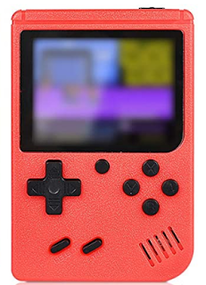
 I bought a couple of those on amazon for 20Euro (yes 2 for 20Euro, one blue, one red) They are incredibly cheap, and surprisingly not crap considering the price. The screen in particular is not too bad. Looks like 2.8' 320x240 screen in parallel mode.  My goal is to put an esp32 inside later on. Let's have a look the power supply / battery. The schematic is more or less that one :  And unless i've missed something, yes the battery is connected to USB through a diode That's it. So since usb is 4.5....5.5v, the battery is connected to 3.9.....4.9v At best , it relies on the battery protection circuit ( if there is one) And if the battery is severely discharged, the charging current will go near 1A, way too much for those cheap batteries. At worst, it will severely overvolt the battery, which will kill it very quickly