Posts

Showing posts from December, 2021

Pre Release : lnDSO150 alpha

Image
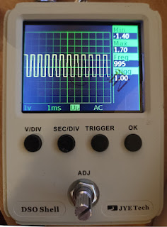
Time to start playing with the new DSO150 firmware: lnDSO150 v2 alpha Be careful of the following : * If you dont have the rotary encoder mod, the rotary encode will not work * If you upgrade from a stock firmware, make sure the watchdog is disabled  * Sometimes,  storing the calibration values will fail. Just retry, it will work * Trigger on both edge does not really work The source code can be compiled to work the same way on STM32F103, GD32F303 and GD32VF103 Github page
lnDSO: float, arm, riscv, wait states

This is an updated version of a previously dealt with topic.  Internally, lnDso is using float to represent voltage. One could argue that it's useless and you can do int->int as the final results are pixel coordinates, but i like to have  the actual measurements available for later processing if need be. It means we have to do ADC value (int)=> volt(float) => pixel(int) In each case the processing is something along output=intput*ramp+offset Let's see how the different chip we can use for lnDSO are performing  (we use rvfp and qfp to have optimised software float lib) - GD32F303 /Cortex M4-FPU@72 Mhz : 7 kCycles - GD32F303 /Cortex M4-NOFPU@72 Mhz : 18 kCycles (~ emulating a cortex M3) Ok, no surprise here,the FPU helps a lot Last but not least , the original MCU on the DSO 150 :  - STM32F103 @72 Mhz : 27 kCycle Ouch. Most probably the flash wait states. - GD32VF103 /RiscV-NOFPU@108 Mhz : 40 kCycles (10 kCycles but the sysTick = cpuClock/4) Not great... /!\ Since we me

lnDSO: Pics of HW modification to use a GD32VF103 (RISCV)

Image
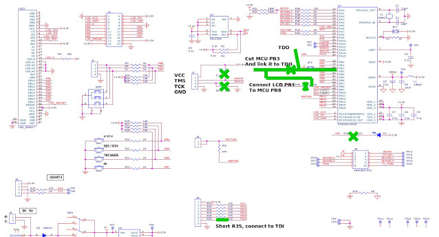
 For reference, here are the modifications to do to replace the STM32F103 (or CH32F103 on some cheap clones) by a GD32VF103 There are 2 extra modifications, unrelated to the VF103 :  * Put a schottky in reverse between r36 and ground to clamp the negative voltage. Probably not needed, but i saw -4 v when testing there. * Replace the diode on the bottom right by a P Mosfet in reverse to avoid wasting 0.6 v there (SH1B). 

lnDSO: Success with GD32VF103

Image
It works ! The first ~ working frankenstein DSO150 with a GD32VF103 RISCV core. As usual, the dumber the mistake is, the harder it is to find In  no special order : - Arm : The vector table must be 512 bytes aligned - Riscv : Dont forget to set the capture pin to ADC mode (the arm version does not care for whatever reason) - When switching the pins from LCD to button, initialize them properly All these are *DUMB* mistakes, but each time it took me a week to figure out why it didnt work.

lnDSO : Slow progress

Image
lnDSO is the successor to DSO-arduino STM32, i.e. alternative firmware for the DSO 150 The main differences are : - It is written using lnArduino, so much more consistent in terms of drivers / low level, compatible with STM32F1/GD32F1/GD32F3/GD32VF103 (yes, i like gigadevice chips). - Capture engine is much better, it should not lose any capture - Much simpler code base, much easier to modify The status so far is:  - it is beginning to work really  nicely on the GD32F303  (my default setup) - untested on STM32F103 but should work easily, the GD32F303 is a enhanced version of GD32F103 which is an enhanced version of STM32F103 imho. - kind of working on the VF103 (RiscV), see image below. It does not capture much :( On the VF103, working around the fact that PB3 is used by jtag  is really a pain. On the DSO 150, PB3 is used on the parrallel bus to the screen but also as the rotary encoder press detection.  The screen is finally working fine with the buttons, the rotary encoder button not