Posts

Showing posts from February, 2021

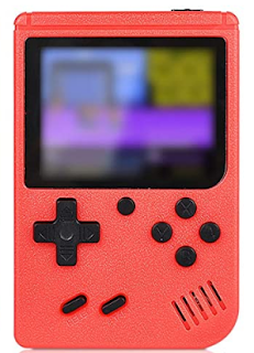
Cheap HandHeld : Reusing the LCD

Image
Edit : Check the next post, it is actually a 16 bits standard 8080 bus I though i could re-use the 320x240 IPS LCD of those cheap units to do other things, there are a lot of test points to solder wires on them and convert them to something easier to use. The connector is 24 pins and a lot of them have fast data signals or VCD/GND. No slow signals such as RD/WR/CS/... I opened the LCD to see if i could identify the chip driving them : couldnt find one So either it's a very very tiny one (unlikely) OR the controller is inside the chip and the LCD is just a LCD (for cost reason) That's a bummer.

Cheap handheld : Using a real headphone jack

Image
Edit: There is a bit too much humming, i'll use a shielded wire. I dont care about the video out, but i do want a headphone jack Let's have a look at the existing headphone jack: It is not a 3.5mm standard jack It is converted by the supplied cable to RCA A/V (composite + mono sound) A quick check showed that the audio is expecting high impedance input and is not able to drive a headphone. Additionally there is a 2.5v DC bias. No problem, let's use the tiny loudspeaker pins instead, it will give a bit too much power, but that should nt be a problem Let's remove the original female jack. The pinout is as follows : The end result looks like that : The new female jack header is super glued to double sided tape, so in theory it can be removed and is strong against push/pull moves. You'll have to file a bit the case , because the jack is bigger. (ignore the RED/BLUE wires, it's just for testing) And it works fine ! Next the LCD.

Cheap handheld : Fixing the battery charging circuit

Image
 Let's use a TP4056 / TP 5100 on the back of the board (there is enough room if you are careful) Schematic change: Basically remove the 2 diodes and the 2ohm resistor add tp4056/tp5100 NB: It's difficult to have the protection working with the TP4056 as the negative battery is connected directly to the PCB ground The battery is ~ 600 mAH (it's written 1020 mAH but you know how it works), so a sweet charging spot is ~ 300 mA With the TP5100 that means R=330 mOhm, i dont have that so i took 2x 1 Ohm = 0.5 Ohm instead to get 200 mA, that's a bit low but well....  (with the TP4056 that would be 4k, much easier to get) The board actually consumes about 200mA That's one problem fixed, i.e. dont stress the battery

Incredibly cheap retro handheld console, battery management

Image
 I bought a couple of those on amazon for 20Euro (yes 2 for 20Euro, one blue, one red) They are incredibly cheap, and surprisingly not crap considering the price. The screen in particular is not too bad. Looks like 2.8' 320x240 screen in parallel mode.  My goal is to put an esp32 inside later on. Let's have a look the power supply / battery. The schematic is more or less that one :  And unless i've missed something, yes the battery is connected to USB through a diode That's it. So since usb is 4.5....5.5v, the battery is connected to 3.9.....4.9v At best , it relies on the battery protection circuit ( if there is one) And if the battery is severely discharged, the charging current will go near 1A, way too much for those cheap batteries. At worst, it will severely overvolt the battery, which will kill it very quickly

DSO150: and even more fun with usb

Image
 There is now a very basic python/qt5 app in the pyDSO folder enabling you to do simple control & capture grab of the DSO 150 It *is* slow but kinda works

DSO150, more fun with USB

Image
Recap :  If you did the usb mod on the DSO150 and use the latest head version of  https://github.com/mean00/DSO_STM32Duino , you can control the DSO150 over the usb link. The pyUsb folder contains several python script to change voltage, timebase etc... Color! One of them (  pySerial_draw.py), enables you to retrieve the current buffer , display it in a window and save the end result as a png. You'll need python3 and python3-opencv2. That script is very small (~ 40 lines) and is just a proof of concept/demo. The end result looks like that: Just a small warning  If you overclock the STM32 you'll probably not have a working usb connection.

DSO150, fun with USB

Image
 I've postponed that from a long time, but finally... Let's assume that you did the USB mode, and run that small python program from DSO150 import DSO150 import csv import time dso=DSO150() print("Asking for a capture ") data=dso.GetData()   f = open('output.csv', 'w') writer = csv.writer(f) writer.writerow(['t','v']) l=len(data) for i in range(0,l):    ns=[i, float(data[i])]    print(ns)    writer.writerow(ns)   f.close()   Connect your DSO150 with my firmware, run the python script and... You end up with output.csv and when imported in your favorite spreadsheet....   Most configuration commands are available through python3/ usb (set voltage, trigger, ask for a capture....) It's very basic for the moment but can be very handy BTW i suck at python too...

mini spot welder : Better schematic

Image
 /!\ May contain errors! Kicad file  link

Reverse engineering mini spot welder control board

Image
 This is revision BL101 2K Schematic of the control board, it may contain errors ! ( V2 , couple of errors fixed) NB : See next post for a more complete schematic

LTC3780, preparing the board

Image
  First, let's remove the 3.3k resistor that ties Feedback to the ground. That's that one : Remove the voltage potentiometer. Ive replaced it with a header. The pinout on the below picture is : FB (RED) VO (Green) VO (Green) Cut the small track between the 2 Vos so that the middle one is connected to nothing. On the back let's put a small perf board (with the usual craftmanship)  that does the wiring described in the previous post, except the digital pot. i.e. So now we have on the pin header : Red : Direct feedback, we'll use that later for current control. Green(middle)  : Voltage potentiometer (0..110k) referenced to ground . Green(bottom) : VOut Power it on with nothing connected : Vo=1.6v = 2xFeedback = as expected since FB=vo/2 (two 100k resistors), the current is very small the diode effect is ~0.

LTC3780 Season 3

Image
 Quick summary of the previous seasons : Season 1 was about adding current limiting to LTC3780 + arduino : Sort of ok Season 2 was about having full digital external control using stm32 + DAcs by redoing the feedback loop completely.  It was more or less working but was very prone to noise i.e. unusable.  (main reason is the LM358 used cannot sink large amount of current => big resistances => noise sensisitve) Season 3 is a hybrid. Let's see what we want : 1- Use digital potentiometers to control voltage & current 2- Make sure it does not blow up when tinkering with it. that means the "unconnected/reset" state should go to a safe output voltage and not crank it up to the max ( i 've blown a couple of transistors that way). 3- Have the control part very close to the DC/DC to limit noise The digital pots i have are 10k & 100K ohm BUT they can only conduct 1mA **MAX** The default LTC3780 configuration is as follows : FB is 0.8, so the max output voltage is