G600 Microscope Battery charging mod
While thinking about replacing the mini usb connector to a micro one on my G600 microscope , i've
seen that post from Syonyk.
Damn ! No real battery charging, straight to 5v.
Warning : This is not an accurate analysis, it may contain errors or missing /misunderstood parts.
Let's have a look. The partially reverse engineered/contains error schematic /picture is as follows :

The equivalent schematic is (incomplete/may contain error) :

So indeed, VBUS (5v) is connected directly to VBAT through just a schottky (K14) and R12.
On the other hand, the BMS circuit is tuned very low and will stop the charge at exactly 4.2 v.
My battery is still healthy and only slightly puffy :)
Let's use a real charging circuit and remove component so that VBUS is completely isolated from VBAT.
Remove K14, the P-Mosfet (Q1) and R54 so that they are really isolated and there is no resistor between VBUS and ground (R54).

I also removed a very small cap/resistor on the other side of the board, but it might not be needed.
Now VBUS is 100% isolated from VBAT.
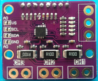
I used a TP5100 to charge the battery, but there is enough space to use a TP4056
I double taped it on the side and added a connector to the battery to easily disconnect it.
Regarding the TP5100 i removed one of the 0.1 / R100 resistor to lower the charging current to 1A

And now it charges safely the battery. Since the BMS is cutting at 4.2 v, the circuit is having a bit of a hard time detecting the charge is complete as it may oscillate just below 4.2v, but it's not really a problem.
The R220 can probably be shorted, but it's so low it's not worth the hassle.
The VCC pin goes to a LDO voltage regulator on the other side of the board that is controlled by the MCU. It is disabled by default, so no current consumption when the unit is off.

You can do this correctly MUCH easier and more quickly (under 10mins) by just:
ReplyDelete1) Removing R12
2) Connecting a single chip TP4056 (most basic version and cheapest of the TP4056 modules) between the VBUS (solder the TP4056 + input to the Anode of your "K14" schottky diode) and the TP4056 + and - outputs to the VBAT battery connection pads in parallel alongside the battery connections.
Simple as that ... by removing the R12 resistor, the shottky diode ("K14"), mossfet (Q1) and pull down resistor (R54) circuit now works correctly to isolate the battery from the rest of the circuit (LOAD) when a USB power source is plugged in and onscreen charging and battery levels are reported correctly while the TP4056 is safely charging the isolated battery.
I think my last paragraph may be a bit confusing so just for clarity and simplicity ...
DeleteI am only removing one component (R12).
Then with short jumper wires soldering only three connections:
1) (IN+) input of the TP4056 module to the "K14" diode Anode.
2) (BAT+) output of the TP4056 to the (BAT+) solder pad on the Microscope PCB.
3) (BAT-) output of the TP4056 to the (BAT-) solder pad on the Microscope PCB.
The battery remains as it was originally (also connected to the BAT + and - pads on the microscope PCB).
By doing that , aren't you bypassing the over current etc... protections of the TP4056/51000 ?
ReplyDeleteAs i understand it, the battery would be directly connected as a power source, and the TPxxx would be only used for charging in a "parrallel" path. Only protections left are in the battery BMS board, as in the original design.
The intent of my mod was to make sure the battery is discharging through the TPXXX and thus benefits from its protections capabilities, and using the BMS as last resort protection.
The TP5100 has internal protections, not all TP4056 have them as it is done by external 8250/DW01 components that might be there or not.
So if your TP4056 does not have those extra chips, i agree, doing the complicated change is pointless
If your TPXXX has protections, i think it is worth doing the extra changes just to be on the safe side.
Might have misunderstood though.
The 2x extra chips on the 3x chip TP4056 more advanced module are the 8205/DW01 combination you mention ... BUT these chips are already on the small battery BMS pcb.
ReplyDeleteSo using the 1x chip TP4056 along with the battery BMS board is pretty much the same as using a 3x chip TP4056 module straight to the battery which is standard good charge control and protection.
*****The main original problem here was that all that was controlling the charging voltage/current was the volt drop across the schottky diode and R12 resistor (which I've seen having different values) and the battery BMS also being used constantly to control the charge cut-off which was 4.3v as this bad method relies on the battery DW01 which as mentioned is a fail safe level and too high.
The use of a basic 1x chip TP4056 module cures all of the original charging control problems with it's voltage/current profiles and the microscope PCB battery charging isolation circuit (diode, mosfet, pull down resistor) works perfectly when R12 is removed.
e.g. when 5v USB power is connected, the gate of Q1 is high so the mosfet is off and the battery is isolated from the load whilst charging under TP4056 control (which it isn't while R12 is in circuit) ... the USB power also powers the microscope circuitry (load) directly but again that is separated from the battery as the BAT+ pad is isolated by the mosfet being off & R12 being removed.
I didn't mean to come across as criticizing what you have done all I wanted to do was offer an easier alternative which gives vastly improved charge/discharge control and adequate protection. IMO adding a 2nd set of 8205/DW01 with the 3x chip module wasn't worth the bother for me.
My unit tests fine here: battery isolates, charges and cuts off at 4.2v properly and IMO the 8250/DW01 chips in the BMS will now function as they are supposed to as a fail safe and not the way they were being used in the problematic original minimum component count design.
I haven't spent any time looking at this in much depth but R12 just seems like a really bad hack along with relying on the battery BMS for charge cut-off control just to keep the pcb component count as low as possible.
I'm always open to suggestions though and if you think I'm missing something please let me know ... :)
You are right.
ReplyDeleteI dont remember completely, but i think i started with something simpler, but when checking with a multimeter, i still had a link between VBus and Vbat. Might have been PBCAK.
How have you connected your circuit back to the PCB? it's not at all clear from the post above.
ReplyDeleteHello,
ReplyDeleteYou can also populated U6 + R5 and remove R12 and R16.
- U6 is a li-ion battery charger ic such as ME4074 (datasheet : https://datasheet.lcsc.com/szlcsc/1808091837_MICRONE-Nanjing-Micro-One-Elec-ME4074AM5G_C236729.pdf)
- R5 is a 0402 resistor for setting the battery current charge (I used a 3K ohm for a 300mA current, see data sheet for other values)
- R12 is a 1206 resistor 0.2 ohm, the battery was charging through this resistor and MUST be removed.
- R16 is a 0402 resistor 0 ohm, it's connect the battery charge led indicator to GND. Remove it and the led will be controlled by U6.
Below some pictures :
https://1drv.ms/u/s!AvXuZk0MdIpUgYgbQlYU5YuLSgtW6w?e=Ga1y3h
Thanks, that's interesting
ReplyDeleteSo the board was meant to have proper charhing circuit, they just "cost optimized it "
Do not be so exaggerated, with the voltage drop in the diode k14 and the small resistance to the battery, about 4.4 or 4.5 volts arrive. No problem.
ReplyDeleteIt works because because of the BMS. If you use a battery without extra cirtcuitry at 4.5v; it will die VERY quickly.
ReplyDeleteI can't see the pictures. Can you fix this? Please.
ReplyDelete