Adding current limit to a cheap dc/dc
This is a hobby of mine.
Let's see what's the goal :
Adding current limiting to a portable power supply based on a cheap buck/boost DC/DC converter.
Additionally , a voltmeter/amp meter module is used.
DC/DC theory (simple)
The DC/DC will convert electricity to magnetic field back and forth, controlling that through a PWM.
It has a "Feedback" pin, and tries to adjust the PWM so that the FB pin has a constant value (1.25 v in my case).
If the FB is below the target value, it will increase the PWM and conversely.
In most case, the feedback is the output of a voltage divider, so that if you change the voltage divider through a variable resistor the voltage will change so that FB sticks at 1.25v (or whatever your DC/DC target value is)

The Feedback value is easy to get, it's the minimum voltage the DC/DC will output.
The important part here, is that the potentiometer has VOut on one side and the Feedback on the other pin.
Current Limiting
The voltmeter/ampmeter module has a shunt resistor value of 10mOhm
How to test it ? Send 1A throught it and measure the voltage.
How does the current limiting work ?
We amplify the different between the max current and the actual current and use it to drive FB through a diode.
If the current is slightly above the limit, once amplified it will drive FB and the voltage will be reduced.
If it is below, the diode will be blocked and the usual output voltage divider will drive FB.
Other simple designs use a simple comparator, but that tends to oscillate quite a lot.
The average value is ok, but the min/max current can be a square pattern.
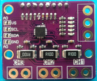
The end result is a small board with the below circuit, used to completely drive FB.
(i.e. we'll move the voltage divider here too).
The two schottky diodes are there so the HIGHER value between V-drive and A-drive is used to control FB.
As said before, we can get both Vout and FB by removing the potentiometer (and the associated 220 Ohm resistor) from the DC/DC board.

NB: There is a 5v power supply omitted here. it is used to power the LM358.
So we first multiply the current sensed through the voltmeter/ampmeter by ~ 220
So the output is Current*220/0.01 Ohm~=Current*2.2
Second, we multiply the difference between the ref and that by ~8
So output = (2.3*Current-Ref)*8
To end up with 1.25v, we need to have 2.3*Current-Ref~ 150 => Current=70+Ref/2.3
The value here are to have current limit settable between ~ 0.1 to 0.9 A
After that it's not limited. How so ?
The LM358 can go up to VCC-1.5v, so it can only go up to ~3.5V
So if the limit set by the potentiometer is above 3.5v, the first LM358 will not be able to output a value greater than that, so the 2nd LM358 will not switch on, whatever the current is.
The part on the top right is to light a LED when the current liming is on.
You can use any small N-mosfet with a threshold of ~ 1v or or less
End result: It works, it is not too noisy except when using very low value current limiting (<100mA)


Comments
Post a Comment