DSO 150: Converting old analog board to new layout ( part 2: ADC Bias)
Now we have to take care of the bias (VBIAS)
For reference, that voltage is used to shift the voltage going to ADC by VCC/2=1.65 v
It is done so that it can sample negative values.
Without it you'd be only seeing positive voltage and all negative voltages would be stuck to ground.
As said previously, the VBIAS was causing a way for noise & temperature sensitivity to creep in.
The old circuit was powering a 3v Zener from unregulated 8v input and using that as a voltage reference to shift the ADC voltage by ~ 1.65v . Since AV+ was ~ 8v, the R28 resistor was passing 5mA ((8v -3v)/1k), so that the zener was fully on. Now AV+ is only 5v, so the current is only 2mA, which is a bit low.

The new board is using the regulated -5v as voltage reference to bias the last stage of the opAmp, like this :

So the change is simple, remove R15 on the old board and replace it by a 3k resistor connected to -5v (AV-)
The exact value you are looking for is 3030 Ohm, 3k +- 1% is fine.
Since we are touching the bias, you'll absolutely need to recalibrate the DSO afterward.
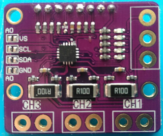
It is mounted that way :

BTW, you'll notice that the last stage gain is different between the old and new boards.This is due to one resistor being different (150 vs 130 Ohm). It's not really a problem.
There is one last optional step to do, get rid of VBIAS completely, that will be for part 3.


Comments
Post a Comment