DSO 150: Converting old analog board to new layout (part 1)
I have 2 DSO 150, one coming from the early models and one recent.
The first models were sensitive to power supply voltage (calibration was changing depending on the power voltage) and to noise.
This has been fixed on later revisions.
The problems come mostly from the analog board power supply.
There are some talks about it on the Jyetech forum
Let's see what we can do.
The old power suppy looks like this :
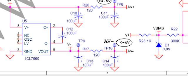
So the input is sent to ICL7660 inverter and the output is used 'as is", without much filtering except the 2x100uf caps.
More annoying VBIAS which is used to shift the input to the middle of the ADC range is also derived from the unfiltered power supply (V+) through a 3v Zener.
That raises 2 issues :
- Not very immune to mid/high frequency noise, i.e. if you use a DC/DC converter for example. Noise will go to the OpAMP power rails AND to VBIAS.
- VBIAS is not a very good ref voltage. It will change a bit if V+ changes and if temperature changes.
JyeTech fixed these problems on the newer analog board PSU :

AV+ and AV- are now filtered/stabilised +-5V out of LM78L05/LM79L05
VBIAS is gone altogether, ADCIN is polarized using AV-, a stable -5v filtered voltage (more on that later).
So let's convert an old analog board to the new layout.
First, let's remove C11/C14/R26/R27 and replace them by LM78L05/LM79L05 and 2x 100nf ceramic caps.
The components to remove are marked here in red :
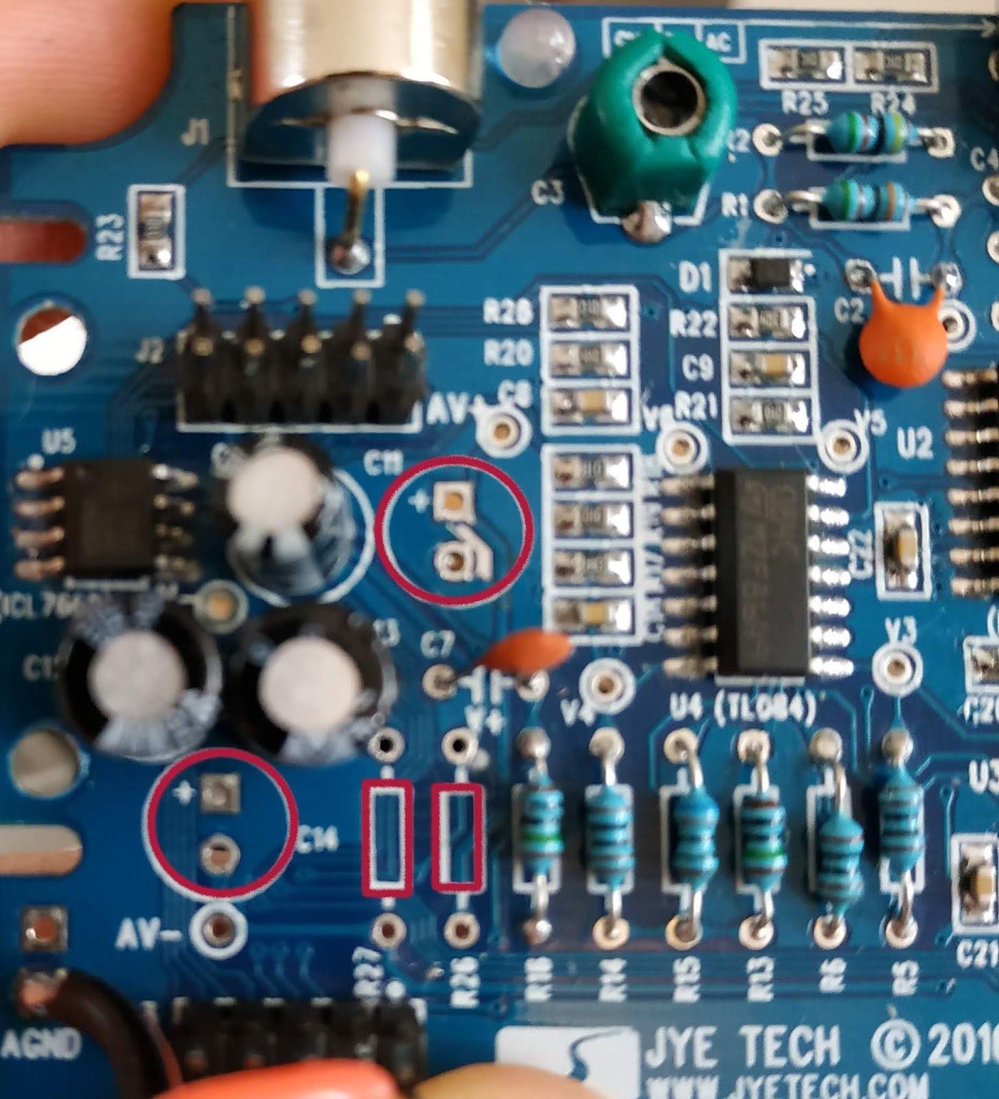
Now put the 78L05/79L05 and the 2 caps using the existing pads. You'll just need 2 wires to connect to the R27/R28 input pads :


You put the LM7xL05 on one side and the 100nf cap on the other side
Let's power it up using the 2nd connector on the top left of the above picture
The pinout is the same between the 2 connectors : Vin & AGnd are on the top right corner
You should have a stable +5v at AV+ and -5V at AV- (you need Vin >= 7v !)
That's part one, but it will not work. You have to take care of ADCIn bias/VBIAS.
As it is now, the zener will have a current of (5v-3v)/1K=2mA which might not be enough
(and we dont want to use that zener anyway)
That will be for part 2.


Comments
Post a Comment