LTC3780 : Back to square one, and now it works
After frying and fixing again the LCT3780 (feedback loop broken, one more time), i realized the current limiting is somehow flawed.
Here is the schematic of the original CC :

The problem is that the feedback (0.8v) is the sum of Isense and Vout * Pot
So the current limiting is not accurate and depends on Vout.
Let's change that, so that only one is used : Voltage or Current mode.
It means the biggest of Vout or Isense is taken into account and the other one is ignored.
Biggest of 2 voltages: it means diodes.
To do that we'll remove the 14k resistor on the board

And cut the track on the other side

(cut at the white mark )
Let's add a very small circuit instead :

We'll have a slight offset generated by the shottky diode (~ 200 mv in my case), but it's constant, it does not matter much.
That becomes (with the usual craftmanship):

The output of that small circuit will be connected to the pad of the 14k resistor we just removed
(the pad closer to the LTC3780)
Bingo, now it's Voltage control OR Current control, not both.
Additionnaly, you can change the 14 k value if you want to (for example if you dont have the right value for the pot), here we used a 15k resistor.
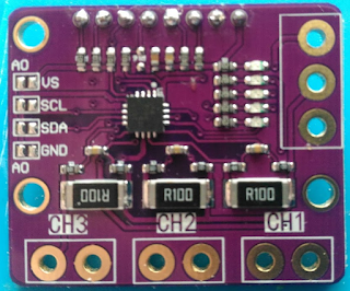
Let's also hook our current sensing board, including the small circuit above and the voltage pot:

It works that way :
The value of 15k has been chosen to be the same load as on the voltage mode.
A difference of ~ 10mA compared to the reference enables the current limiting part of the feedback to get above 0.8+0.2 on the feedback board and so it takes over.
The 2nd stage of the LM358 is a difference amplifier rather than the previous version which was a simple comparator. The comparator was too harsh and the whole circuit tended to oscillate between 0 and non limited Vout.
But how is the reference voltage (i.e. max current value) supplied ?
The code allows 2 methods :
and.....
It works fine !
Except there is a lot of ripple, about 200 mv for 5v output, even worse when CC kicks in.
So let's add a LC filter at the output of the LTC3780

Ripple ~ 15 mV when in Voltage mode
~ 50 mv when in Current mode
The ripple goes down when voltage goes up, to 6 mv or so. It is due to the filter having ~ 2kHz resonnance frequency corresponding to 3 v or so.
Not bad. It tends to drift a tiny bit though, might be a side effect of all the modifications i've done + repairs.
There is still a bug in the simpler_INA219 lib to iron out and the whole thing tends to be finicky when booting is concerned, but overall it is in line with my expectations.
Here is the schematic of the original CC :

The problem is that the feedback (0.8v) is the sum of Isense and Vout * Pot
So the current limiting is not accurate and depends on Vout.
Let's change that, so that only one is used : Voltage or Current mode.
It means the biggest of Vout or Isense is taken into account and the other one is ignored.
Biggest of 2 voltages: it means diodes.
To do that we'll remove the 14k resistor on the board

And cut the track on the other side

(cut at the white mark )
Let's add a very small circuit instead :

We'll have a slight offset generated by the shottky diode (~ 200 mv in my case), but it's constant, it does not matter much.
That becomes (with the usual craftmanship):

The output of that small circuit will be connected to the pad of the 14k resistor we just removed
(the pad closer to the LTC3780)
Bingo, now it's Voltage control OR Current control, not both.
Additionnaly, you can change the 14 k value if you want to (for example if you dont have the right value for the pot), here we used a 15k resistor.
Let's also hook our current sensing board, including the small circuit above and the voltage pot:

It works that way :
- The INA219 has a 20 mOhm shunt to get back a current reading
- The voltage across that same shunt is multiplied by 23 by the first stage of the LM358 (output is now 0.46*I
- The difference between that and a reference voltage is multiplied by 101 by the 2nd stage of the LM358
- The output of the 2nd stage is send to the feedback board through a 22k/15k voltage divider.
The value of 15k has been chosen to be the same load as on the voltage mode.
A difference of ~ 10mA compared to the reference enables the current limiting part of the feedback to get above 0.8+0.2 on the feedback board and so it takes over.
The 2nd stage of the LM358 is a difference amplifier rather than the previous version which was a simple comparator. The comparator was too harsh and the whole circuit tended to oscillate between 0 and non limited Vout.
But how is the reference voltage (i.e. max current value) supplied ?
The code allows 2 methods :
- Through a simple pot (value must be low enough , dont use 1M pot....)
- Through a 12 bits i2c dac, much better. I used a MCP4725 which is cheap and easy to program.
and.....
It works fine !
Except there is a lot of ripple, about 200 mv for 5v output, even worse when CC kicks in.
So let's add a LC filter at the output of the LTC3780

Ripple ~ 15 mV when in Voltage mode
~ 50 mv when in Current mode
The ripple goes down when voltage goes up, to 6 mv or so. It is due to the filter having ~ 2kHz resonnance frequency corresponding to 3 v or so.
Not bad. It tends to drift a tiny bit though, might be a side effect of all the modifications i've done + repairs.
There is still a bug in the simpler_INA219 lib to iron out and the whole thing tends to be finicky when booting is concerned, but overall it is in line with my expectations.


Comments
Post a Comment