LTC3780 Current limiting, low side
/!\ There is a much better version of that in the "going to square one" post
http://goingbacktoelectronic.blogspot.fr/2018/01/ltc3780-back-to-square-one.html
The circuit is pretty simple :
The left part generates +5v / -5v from the 7.5v coming from the power supply board.
It is to make the LM358 work as much as possible in its linear zone.
That way, it is linear down to 10mA, which is accurate enough.
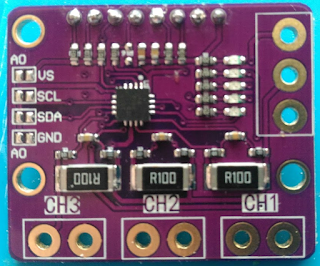
The shunt voltage is then amplified by 23, so with a 22 mOhm shunt, we amplify the current by 22 mOhm*23 = ~ 0.5
I measured the output voltage to be : OutputVoltage = 0.52 x Current + 42 mV
It does not have to be super accurate, since we'll calibrate it later.
Same for the voltage offset (42mV in my case), since we do a comparison afterward, it does not matter much as long as we correct the offset to display the right value.
Last, we compare the output to the MaxInput. If it is higher, we pull up the feedback pin.
Note that if maxInput is > 3.5 V, there will be no limiting at all

The whole thing is consuming between 5 and 10 mA
The actual thing (i know ....)

We have options as how to drive maxInput pin :
- through a simple pot
- through an arduino analog pin.
- through a pot + log amplifier


Comments
Post a Comment