Posts

DSO150 Playing with floats & speed

  My version of the DSO 150 firmware is using float internally to convert ADC to voltage. It could probably be faster using 32 bits fixed point, but float is good enough for now. Let''s see how it evolves, the basic test is converting 240 samples from ADC to voltage For each sample the formula is OUT=IN*multiplier - Offset STM32F103 overclocked to 128 Mhz "Old code" : 880 us "Newer code" afer optimization : 440 us Using fast float lib (qfp) : 380 us So twice as fast, not bad GD32F303 at 96 Mhz It is a cortex M4 core with FPU "Newer code" without FPU : 350 us "Newer code" with FPU : 83 us
STM32 Based component tester

 No recent news recently on the  STM32 based component tester So a quick summary : * Supports STM32F103/GD32F103 (borderline in term of flash size)/GD32F303 * Resistors * Capacitors down to ~ 10 pf * Diodes (with VThr < 3 v) * NPN & PNP transistors (hFE, Diode voltage) * N &  P Mosfets (Vgsthresh, RdsOn, Diode) The only ones i cannot figure out are coils.

Adding current limit to a cheap dc/dc

Image
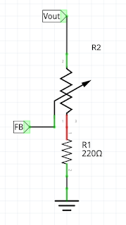
 This is a hobby of mine. Let's see what's the goal : Adding current limiting to a portable power supply based on a cheap buck/boost DC/DC converter. Additionally , a voltmeter/amp meter module is used. DC/DC theory (simple) The DC/DC will convert electricity to magnetic field back and forth, controlling that through a PWM. It has a "Feedback" pin, and tries to adjust the PWM so that the FB pin has a constant value (1.25 v in my case). If the FB is below the target value, it will increase the PWM and conversely. In most case, the feedback is the output of a voltage divider, so that if you change the voltage divider through a variable resistor the voltage will change so that FB sticks at 1.25v (or whatever your DC/DC target value is) The Feedback value is easy to get, it's the minimum voltage the DC/DC will output. The important part here, is that the potentiometer has VOut on one side and the Feedback on the other pin. Current Limiting The voltmeter/ampmeter modul...

codium+blackMagic on linux

 It was not easy to have it running Most of the answer is coming from that post : http://www.martinhubacek.cz/arm/black-magic-probe-vs-code The linux version of launch/json  is as follows (~ almost the same): { // Use IntelliSense to learn about possible attributes. // Hover to view descriptions of existing attributes. // For more information, visit: https://go.microsoft.com/fwlink/?linkid=830387 "version" : "0.2.0" , "configurations" : [ { "name" : "BMP (gdb) Launch" , "type" : "cppdbg" , "request" : "launch" , "MIDebuggerPath" : "/home/fx/Arduino_stm32/arm-none-eabi-gcc/download/gcc-arm-none-eabi-8.2.1-1.7/bin/arm-none-eabi-gdb-py" , "targetArchitecture" : "arm" , "program" : "${workspaceFolder}/build/componentTester_STM32F103.elf" , ...

Stroboscopic ADC- follow up, VERY LOW capacitors

 I've spent a lot of times on this due to a silly bug. The sillier it is , the harder it is to find out. Now, it works fine. For reference, we sample a cyclic waveform, repeating every N cycles by sampling it every N+x cycles. That gives an apparent sampling period of x. In our case, for the STM32/GD32, the higher sampling frequency is 72M/PWM divider (1 or 2)  (96M for the GD32). That gives an equivalent smallest sampling period  of 14nS (10 nS for GD32), compared to the 500 ns maximum using the "regular" method. Let's inject that into our capacitor measurement stuff and check the results : C Me M328 0 N/A N/A 3 2,54 N/A 10 9,65 N/A 20 19,4 N/A 47 47,6 52 56 55,6 60 68 70 75 100 96,8 101 220 231 232 310 323 330 The first column is the value written on the tin The second column is the value measured by our tester The 3rd column is the value measured by a M328 transistor tester (cheap chinese version) Not too bad, and we can go down to ~ 2pF. The main drawback of that ...

SSD1306 : From SPI to I2C

Image
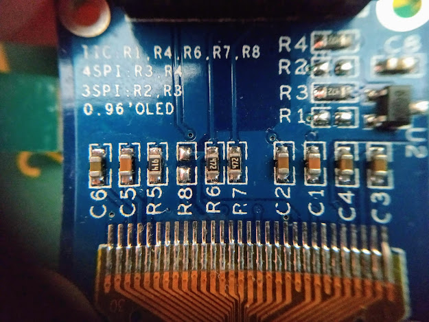
Sometimes you need/want to use I2C rather than SPI A very popular LCD screen is the SSD1306 Oled 0.96' display They are cheap and very well supported. The back looks like this : The change is easy, link the R8 marks and move the resistor from R3 to R1 These are the marked ones here: You end up with that  D0 is now i2c clock D1 is now I2c data You need these two + the reset pin and you are good to go.

Measuring low level cap/inductance and stroboscopic mode

The scheme we have used so far to measure capacitor is to generate a square pulse and capture the voltage waveform.   For reference, the STM32/GD32 MCUs have very decent 12 bits ADC that can go down to ~ 0.5/1us sampling frequency. For capacitors, the time constant of the waveform is proportional to Resistor*Capacitance, so if we use the bigger resistance (470k) we can have a few points even with very small caps. NB: The waveform is V*(1-exp(t/RC)), so with 2 known points we can calculate R*C. Since R is known , C can be computed. It gets problematic with inductance.  The time constant is proportional to L/R, so with the smallest R (470 Ohm) and 100 uH inductance that leads to time constant  in the order of ~ 100E-6/470= 200 ns, which is way too small compared to the ~0.5/1 us resolution of the ADC. Additionally, we need at least something like 5 points to have a valid guesstimate. So we are out by a factor of 10. I've been scratching my head on that one for some ti...