Posts

Cheap SpotWelder : Replacement Control Board

Image
  This is the prototype board for the Cheap Spot Welder control board. It is a drop-in replacement for the original control board. It is based on a STM32F1 / bluepill board with a SSD1306 Oled screen, a rotary encoder, and a buzzer salvaged from an old 3D printer board. What does it bring ? Not much, it's cheap to make (<10$), it's opensource, it is easy to tune / change and it's massive overkill :) On the othe hand, a bluepill board is very cheap ~ 2$, so no point in trying to make something with a smaller MCU. It even runs freeRTOS. This is very much work in progress, all the building blocks are there, just need to do the magic sauce to glue all of them together.

Mini 360 DC/DC converter : avoid !

Image
  For the spot welder replacement board, i wanted to use a DC/DC converter to lower the 12v input voltage to something smaller (5V). The aim is to avoid heat and lower the current consumption, so that there will be no problem when the spot welding happens. The original boards consume about 10 mA, the STM32F1 based one consumes about 50 mA. I happened to have several of those mini 360 DC/DC converters. They are based on MP2307. The bluepill needs about 50 mA at 5v idling. The DC/DC is powered by 12V, outputs 5V  and needs ...70 mA! WTF ? I tested it with no load at all, still ~70 mA Changing the self and/or the output cap and/or the load makes the consumption varies a lot, between 7mA to 80 mA+load. Additionally the output oscillates , +- 0.5v at high frequency. From what i could see with a quick check, it needs a self/cap/... tuned to the input/output/load settings and if you dont have the right ones it will heat up and have a very bad efficiency. So unless you know you are in...

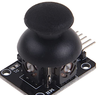
Using Analog stick

Image
  Still planning to pimping the cheap handheld console, so i bought a few of these cheap analog sticks. They are pretty simple, just 2 rotary potentiometers, converting the angle to a voltage divider. The voltage is VCC/2*(1+sin(Angle)) With angle from -90 degree to + 90 degree  A simple lookup table will easily invert that, to get the angle from the voltage.

Cheap handheld, a closer look at the screen

Image
It seems the screen is a fairly standard 16 bits parallel interface driven by ILI9341 style controller. The following annotated picture contains  a lot of guesswork, but this is how it seems to be connected : The main issue is finding how to switch it to 8 bits parallel instead of 16 bits.

Cheap HandHeld : Reusing the LCD

Image
Edit : Check the next post, it is actually a 16 bits standard 8080 bus I though i could re-use the 320x240 IPS LCD of those cheap units to do other things, there are a lot of test points to solder wires on them and convert them to something easier to use. The connector is 24 pins and a lot of them have fast data signals or VCD/GND. No slow signals such as RD/WR/CS/... I opened the LCD to see if i could identify the chip driving them : couldnt find one So either it's a very very tiny one (unlikely) OR the controller is inside the chip and the LCD is just a LCD (for cost reason) That's a bummer.

Cheap handheld : Using a real headphone jack

Image
Edit: There is a bit too much humming, i'll use a shielded wire. I dont care about the video out, but i do want a headphone jack Let's have a look at the existing headphone jack: It is not a 3.5mm standard jack It is converted by the supplied cable to RCA A/V (composite + mono sound) A quick check showed that the audio is expecting high impedance input and is not able to drive a headphone. Additionally there is a 2.5v DC bias. No problem, let's use the tiny loudspeaker pins instead, it will give a bit too much power, but that should nt be a problem Let's remove the original female jack. The pinout is as follows : The end result looks like that : The new female jack header is super glued to double sided tape, so in theory it can be removed and is strong against push/pull moves. You'll have to file a bit the case , because the jack is bigger. (ignore the RED/BLUE wires, it's just for testing) And it works fine ! Next the LCD.

Cheap handheld : Fixing the battery charging circuit

Image
 Let's use a TP4056 / TP 5100 on the back of the board (there is enough room if you are careful) Schematic change: Basically remove the 2 diodes and the 2ohm resistor add tp4056/tp5100 NB: It's difficult to have the protection working with the TP4056 as the negative battery is connected directly to the PCB ground The battery is ~ 600 mAH (it's written 1020 mAH but you know how it works), so a sweet charging spot is ~ 300 mA With the TP5100 that means R=330 mOhm, i dont have that so i took 2x 1 Ohm = 0.5 Ohm instead to get 200 mA, that's a bit low but well....  (with the TP4056 that would be 4k, much easier to get) The board actually consumes about 200mA That's one problem fixed, i.e. dont stress the battery