Posts

Flicker Free ILI9341 : How it worked, how it works

Image
Before : So how was it drawing variable width font ? The crude schematic below explains it : For each character, only a portion of the occupied space was actually painted (the orange square ) The Area between X=0 and X=Xoff was untouched, same for above/below/right side. That's why there was leftovers of the previous content if you just print on top of it. After: The trick is pretty simple : Fill with background image those areas and draw the font as usual, AND use the block mode for increased speed. To do that we'll precompute one or two lines in memory and blit it all at once. Why only one or two ? To reduce the memory consumption. If we dont do that, for large font (say 64x64), we would need 64*64*2 =8 kB of ram, that's way too much. The only part left is the part after the text For that we add an additional optional paramater (maxWidth) that will be filled with background color. So the total area is filled whatever the actual size of the text...

i2c controlled power supply : Flicker free ILI9341 - The problem

I bought a few ILI9341 LCD screens on ebay. I intend to use them for the i2c controlled power supply. Why those ? They are cheap, big enough Using the block update, they are fast. Basically define a rectangle on the screen and send all the data in one transaction. This is much faster than drawing  pixel per pixel or even line by line We have a nice driver for STM32 -arduino using that blockmode. That driver is indeed very fast. With one issue : font management Going back in time, that driver is derived from the Adafruit one With the Adafruit one, you can use pseudo ttf font, with variable width/height.  Pick any font you like, use fontconvert to generate the fontxxxxx .h and done. Since they are variable width, the result looks natural. The problem is when overwriting. Since it is variable width/height you cannot just overwrite the old text with the new one, some leftovers may stick. For example, replacing "ZZZZ" by "llll" will cr...

Power Supply, i2c controlled continued

Image
Time to actually test the concept : The schematic is below.  You'll note it is probably overkill, lots of follower opAmp to avoid impedance troubles, but LM358 are really cheap, so not worth the trouble. The only downside is they consume lots of space on the board, unplanned originally. The Voltage/Max current references are given by two MCP4725 12 bits DAC. They have 2 interesting features : They are very cheap They can be programmed to have a default value. We'll take  500 mv so that vout = 500mv*11= 5.5 v by default, and 100 mv=>100mA for default max current. They are driven by a 3.3v rail, so that they can be interfaced with STM32 later without extra check. One thing has been added : If FBI > FBV, it means we are in current control mode, so the CC pin will go high (+ a SMD LED will lit up) Preliminary testing shows it works fine, except it seems a bit slow to converge. Need to look into that closer at a later time. The usual messy ...

Bench power supply revisited: Digital Control

Image
The usual way to control a DC/DC power supply is to send a fraction of the output voltage to the feedback pin. The fraction-ing is done using a potentiometer i.e. a resistance divider. The DC/DC converter will adapt the output voltage  so that the feedback pin reaches a constant value (typically 0.8v or 1.2v) If Vo*Divider < 1.2 v, the DC/DC will increase Vout If Vo*Divider > 1.2 v, the DC/DCDC will decrease Vout Nice ans simple , but two caveats : You cannot have Vo < Feedback, so not possible to do 0.5v for example It cannot be controlled digitally. Using a digital potentiometer is not really an option. They have strong limitations regarding voltage and resistance. So instead, what we will do is directly drive the feedback pin in a slightly more complicated way. To do that, we add a difference amplifier to compare 1/11th of Vout to a voltage reference (Vref). That voltage Vref will be set digitally. Same story as before, if Vout/11 ...

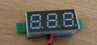
Converting 2 wires cheap voltmeter to 3 wires

Image
You can find these very cheap voltmeters all over ebay. They have a single wire for both power supply and volt measurement. No surprise, they need enough voltage to power up the circuit and display, that is ~ 3.3 v As a result they are  useless to display lower voltage. If we flip them, the power supply part is simple enough : On the Top left,there is a diode marked as D1 (reverse polarity protection), followed by a 7133H  voltage regulator on the bottom left to get 3.3 v. Just remove the diode and connect 5v power supply there Done ! Now you can measure much lower voltage. It might be a good idea to put back a reverse polarity protection diode somewhere ....

Unclogging 3d printer nozzle with kanthal

Image
Pretty often, a 3d printer  nozzle gets clogged when impurities get stuck in there. You can buy expensive and brittle very fin drill bits or... Use vaping gear (again) : Take a 0.3 mm kanthal, it is a  commonly used size , perfect to unclog a 0.4 mm nozzle. The kanthal can take the heat and is strong enough 1- Heat the nozzle with hot air gun at 200 degrees 2- Push a strand of kanthal inside the hole 3- Remove all the gunk Done ! It is way more gentle that drilling it

Battery tester mark 2

Image
So after solving the resistor ballast issue, let's have a look at the battery tester v2. What are the requirements ? Big color screen. Because it is prettier. Constant current discharge up to 1.x Amp. We mostly target 500 mA, voltage between 3 and 5v Rotary encoder to do the setup The screen will be a 320x240 ILI9341, you can get them on ebay for ~ 4$ We'll use a STM32F103 micro controller to drive it. Why ? Because it is much better than a cheap Atmel based board : 64 or 128 kB Flash, 20 kB Ram MUCH faster Cheap (~ 2$) You can actually debug with it, using a STLINK V2 clone or a blackmagic clone. The ATMEL chip is too slow to drive such a screen. Run at 3.3V, which is perfect for the ILI9341 which also runs at 3.3v on its IOs. Let's have a look a the constant current circuitry : The QUCS  simulation file is available here  on github . So we just have to provide VREF and the current will be adjusted to follow it. The simulator output...