Posts

Let's try to make an ESR meter (part 1: AC Signal)
Image
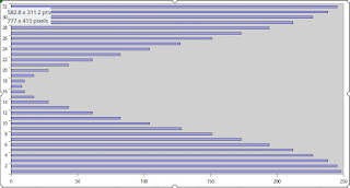
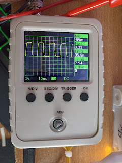
 I've stumbled upon this : https://ludens.cl/Electron/esr/esr.html A 100% hw ESR meter. The principle is simple enough :  - Generate an "AC" signal - Go through a transformer to lower voltage/increase current  - Measure the impedance across the capacitor to measure (and assume ESR >> Z at that fq ?) Let's do it with a MCU and a salvaged transformer from a 5v usb power supply. AC ? Since we are using a transformer, we NEED to use a AC source. DC will just heat the transformer. At first i used a sine oscillator made with an opamp, it sort of worked but was very unreliable in terms of replicating the circuit (gain was to be manually tweaked, its oscillation was changing, single fq ...) The 2nd try was with a plain square oscillator, driven by the MCU. It worked fine, but caused inductance effect on the transformer because the signal was square. The transformer output signal was very distorted. I could have used a CH32F103 or a GD32Fxx, which contain a DAC, but i a...

Mixing C++ and Rust on a small embedded system

  This has been one of my pet project for some times now, mixing lnArduino  drivers ( hardwired to STM32F1 / GD32VF1 *AND* FreeRTOS) with  rust code. Why ? Because rust is fun :). There are a lot of gotchas, your mileage may varies, you may disagree with me. Below is the current status, in case it helps others.  I do not pretend to bring you the "truth"/"the right way to do it", this is just my journey so far. Building with cmake Corrosion  is a very nice project , that makes mixing Cargo based project and cmake project a breeze.  . Really no problem here. Interworking Calling C++ from rust and conversely is a bit hit & miss. The current setup i'm using is to use bindgen to generate a first layer of rust binding  AND THEN , on top of that, manually write  a very thin rust wrapper to get rid of the unsafe {}, have a cleaner API, and add the missing pieces. For example, bindgen cannot deal with pure virtual c++ function, so you have to add a int...

1.69' ST7789 240x280 rounded corner LCD

Image
 That screen is available for ~ 4$ on  ebay It has a few oddities. First the pinout, it is not easy to find but here it is : 1 GND 2 LEDK (connect to ground) 3 LEDA (connect to VCC with a few ohms resistor, like 10 Ohms) 4 VCC 5 GND 6 GND 7 DC 8 CS 9 SCL    (SPI Clock) 10 SDA  (SPI Data) 11 RESET 12 GND Second, it is a bidirectional SPI, meaning only 2 pins are used: Clock and Data Data is used for both as MOSI and MISO depending on the command. On those screen, reading is seldom used, so you could just use it as MOSI. The logical screen is a plain square 240x280 box, some pixels are just not physically there.  

lnDSO150 : Release 2.2

Image
Binaries available for Jyetech, GD32F303 and FNIRSI  https://github.com/mean00/lnDSO150 Be sure to check the wiki to know how to flash

CH32F103/FNIRSI: Success!

Image
 Still some minor tweaks to apply, but it works 

CH32F103/DSO150/FINRSI coupling selection difference

 There is another difference with the original DSO : CPLSEL pin With the original DSO, the CPLSEL (PA5) is an analog pin which gives the info about the selected coupling. When reading it with the ADC, you get : -   0 => GND -  ~ 2024=> DC -  4095 => AC (not necessarily the right values, but the principle stands). The FINRSI clone is different. It uses the CPLSEL pin *AND * another pin the "KEY" pin (PB12). That pin  was used a long time ago but is no longer needed as the threshold detection is done using the ADC watchdog Both CPLSEL and KEY are pull up GND:    CPLSEL=1   KEY=1 AC:    CPLSEL= 1    KEY= 0 DC   CPLSEL=0   Key=1 So it wastes one pin, but makes the reading much much more simple. NB: The CH32 only has one ADC, that may explain.

lnDSO150 : DFU ready for STM32F103 and GD32F303

Software is ready and works fine if you have 128 kB of flash or more. Sofwtare update over usb at last ! A lnDSO150 release will be coming soon, as soon as the CH32 chip works.
