Posts

More esp32c3/jtag

Image
 Using the embedded usb/jtag link with the esp32c3 was really unstable.  Once in a blue moon it was usable  (tried on 2 modules). So let's consume more pins and have something that works better : 1- Step 1: Be sure you have a recent esptool (  https://github.com/espressif/esptool ) 2- Step 2: We'll burn the JTAG_SEL efuse so that the jtag is connected to either the internal usb stuff or the IO4...IO7 pins depending on the state of IO10 at reset espefuse.py  burn_efuse JTAG_SEL_ENABLE 3- Step3 : Hardwire IO10 to ground, that way we force the jtag on the external pins 4- Step 4: Connect your favorite Jtag probe , the mapping is as follows :     TDO IO07     TCK IO06     TDI  IO05    TMS IO04 /!\ Important: make sure you have some *not* brain dead code programmed in. If the chip deep crashes right at start, even the  jtag will not work properly. The default way to set it up ( from what i understood) is as follows : ...

Playing with another RiscV chip : ESP32C3 , Jtag adventures

Image
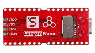
While still having fun with the GD32FV103, which are very good low end MCU,   I also bought a few cheap esp32c3 boards on aliexpress, like those ones (esp32c3 32S) Installed everything, built hello world, all is fine. Now time to have a real debugger. openocd installed, gdb ready, let's go. According to the nice documentation, the jtag/serial-to-usb bridge is included in the chip, no need for a FTDI or similar. Great ! Problem is, when connecting the board to my linux, it only detects a CH340 serial to usb chip, which is indeed present (it's the big black rectangle at the bottom). Ok, no problem, we'll use directly TDI/TDO/TMS/TCK aka GPIO 5/7/4/6 with a ftdi. Does not work either .... Ok it seems that the jtag, by default , is routed to the internal USB component which is not connected. Two options here from what i understood : * Blowing efuse to change the connection from internal usb to external pins. Should work, but we'll lose 4 gpios, that' s a bit too much. W...

Inductance tester , continued

 I tried previously to measure the inductance of a coil using the same method as for capacitors : take 2 points in the charge/discharge curve and compute the L value After a pulse on the coil, the voltage across it is (1-exp(-t*R/L)), so if we have t, R and 2 points we can compute L. The problem with inductance is the curve is very very small, like ~ 1us, way too fast for the ADC, and using very small R will give high current. Recently i saw a youtube video from DiodeGoneWild ,  he showed his own inductance meter It's 100% pure analog, no MCU. How does it work ? It sends GND/VCC squares to the coil do trigger charges/discharges. A schmidt trigger creates a nice square when coil voltage is between 1/3 and 2/3 vcc. The duration of the square gives the inductance. Measuring a small-ish duration is not easy to do with analog circuits so that's how it does it : since a PWM is charging/discharging the coil and generates squares, the output squares are integrated though a 2nd order l...

T7 component tester teardown

Image
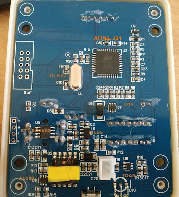
 I bought this unit for cheap on amazon. Didnt really play with it until i wanted to check something on a vanilla NPN transistor.  It gave a hFE of 426.  Really ? That's a bit high, i checked with my own tester and the datasheet, they both gave around 250. Okay, time to open it up : The MCU is an Atmel 324 with a 16 Mhz quartz There is a second tiny MCU a STC 8G1K08 (??) The AL088 is maybe a step up converter circuit The 7DA5 is probably a lithium charging circuit V05 are TVS Build quality is fine, just a bit of flux i cleaned up There is also a "431" on the top right, probably a TL431 voltage reference for the ADC.

GD32/STM32 : WS2812B using Timer + DMA

Spi not good enough for  you?  The easy way to use WS2812B programmable RGB leds is using the SPI MOSI pin. That works fine most of the times with a couple of gotchas : The SPI divider is not very flexible on the GD32/STM32 chips, you can only divide by a power of 2. So if your APB clock is not "near"  enought the WS2812B 400 us tick you are in trouble or must use complicated schemes. Using a SPI "locks" the alternate functions of ~ 4 pins. So you can't use them for PMW or any other alternate functions, even if you dont actually use them. The SPI pin is the one getting killed most often on my boards. I have a few MCUs that are working fine except the spi is fried.  Also the 2nd /3rd SPI are using APB1, so not ok in terms of clock. In short, Spi0 @ 72 Mhz is ok, other setup is to be looked closely at. What's the other option ? The other option is to use PWM + DMA. We program a 1.2 us PWM mode 0 on a pin. We change the duty at every cycle to create 0s and 1s. ...

GD32 + Non volatile Memory : NeVerMind

Image
  I'm porting the spotwelder control board from stm32duino to lnArduino, so that i can use indifferently a STM32F1/GD32F1/F3/VF3 and to have a smaller and better codebase. It had a couple of tiny bugs but it is working sort of ok. Then  i reached the last missing piece : Non volatile memory. The Stm32duino version is using the eeprom emulation code from STM that can only store couple (id,value) with value on 16 bits.  It works  but it's a bit awkard to use if you want to store 32 bits stuff or floats. Additionally, the license is a bit restrictive it seems. On the other end of the spectrum, you can switch to tinyFS. But this is way overkill to store some basic settings. I looked on github without finding something suitable. What do we want ? Sort of robust if interrupted during a write ( ~ atomic) Variable size writes (with a small maximum) Not erasing the flash at every write Since i couldn't find something suitable,  i wrote a quick & dirty non volatile me...

Blackmagic + gdbgui

Image
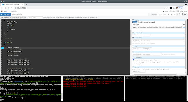
 Sometimes it really helps to have a nice GUI for GDB Finding an IDE that supports *correctly* remote gdb debugging as used with Arm or RiscV boards is difficult. There is one option that seems to work ok :  gdbgui The principle is that the UI is actually your favorite browser How to start it easily with the backmagic ? 1- create a blackmagic gdb init script target extended-remote /dev/ttyBmpGdb monitor connect_srst enable monitor swdp_scan attach 1 load compare-sections set mem inaccessible-by-default off set confirm off 2- start gdbgui through a small shell script #!/bin/bash export F=$PWD/$@ echo "Loading $F" gdbgui -g "/home/fx/Arduino_stm32/arm-gcc-2020q4/bin/arm-none-eabi-gdb-py3 -x /home/fx/blackmagic.gdb ${F}" (you'll need to adapt those 2 scripts for your configuration : path to gdb, path to blackmagic.gdb, device to use etc...) then bash ~/gdbgui.sh myelf.elf and it starts.  A small warning, i have to go to the output panel and press enter or else it...