Posts

Fun(?) with amazon fake review detector

A few weeks back i received an email from Amazon(.fr) saying that i was barred from posting comments, that all my previous comments were deleted, because i violated the rules, nothing more specific. What the fuck is that  ? I contacted the client support , multiple times and i will sum it up here what i've found in case it happens to someone else: They (support) can't do anything about it directly They don't even know what triggered it They can only send a request to a dedicated service that will "contact you by email" (maybe, after a while, dont hold your breath on it). That service is not reachable by email, chat nor phone. And sometimes, they lie by assuring you it will be fixed within 24h or 48h or that it is a "system wide issue" or anything else to make you give them a good mark. How lame. It took ~3 weeks to have this fixed. I finally received an email saying it was a mistake and it was all fixed. End of story ? Not really....

Protecting the LTC3780 (or other DC/DC converter)

Image
The main problem when playing with LTC3780 (or other) is it can fry easily. Especially when you are playing with the feedback loop. How so ? Easy, just disconnect the feedback pin, it will crank up the output voltage to the max and burn As a bonus, it will also fry what's connected to it if they don't like higher voltage. So here, we'll add a very simple protection circuit : An enable pin that turns the LTC off by default, i.e. if the signal is not driven A shutdown circuit if the output voltage exceeds ~ 28v The right side is glued to the DC/DC converter The left side is on the control board. If the Enable pin is high (or floating), the STBY pin is pulled down and the DC/DC turns off Similarly, if Vout exceeds ~ 26 V, STBY is pulled down, and the DC/DC turns off Very primitive, but that should help when connecting/disconnecting stuff all the time NB: If you use another N-FET (Q4), you'll have to change R9 to something else T...

i3Mega : Adding glass bed

Image
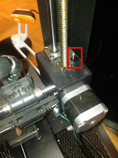
Anycubic i3 Mega & ABS I've discovered the hard way that the only working method for me to print ABS is to use ABS glue. I.e. ABS dissolved in acetone. Add a thin layer on the printing bed and that dramatically increases stickiness. Printing ABS that way is a breeze (a smelly breeze actually). So problem solved ? Not really. Cleaning the ABS glue on the i3 mega is messy, smelly and takes a lot of times. You have to pour acetone, scratch the bed gently with a toothbrush, again and again and again I've never managed to completely clean it up. There are still some smears of ABS glue today.  I guess i'd have to remove the bed and clean it up externally. So i wondered : What if i had a borosilicate glass on top of the original bed ? That would be easy to clean up. So, here we go. I ordered one on amazon , with metal large paper clips (should have taken bigger ones, but they do work). The problem is now how do we compensate for the ~ 3 mm offset on the...

blackmagic part 2 : Software under linux

The blackmagic will show itself as 2 ttyACM devices They can have different names depending on what is connected to the system To solve that, following the blackmagic wiki, the simplest is to create a file in /etc/udev/rules.d/10-blackmagic.rules containing                                           SUBSYSTEM=="tty", ATTRS{interface}=="Black Magic GDB Server", SYMLINK+="ttyBmpGdb" SUBSYSTEM=="tty", ATTRS{interface}=="Black Magic UART Port",SYMLINK+="ttyBmpTarg"   Reboot or use udevadm trigger  , replug the blackmagic and you should see two  devices  /dev/ttyBmpGdb and /dev/ttyBmpTarg These names will stay the same Next, let's write two simple shell scripts to make our life easier : blackmagic.sh: This will flash the file given as argument #!/bin/sh export PORT=ttyBmpGdb ${PREFIX}arm-none-eabi-gdb -ex "target extended-remote /dev/$PORT" -ex ...

Building your own blackmagic using cheap bluepill board

Image
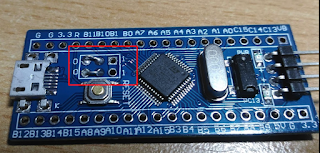
Let's build a nice bluepill based blackmagic debugger. why is it worth it ? because it makes it possible to debug a stm32 sw using your usual gdb / gdb frontend VERY easily Shopping list * Bluepill from ebay * 3S1P battery connector + wire Firmware First you need to flash the board with "bluepill" blackmagic firmware. It does not compile out of the box, there is a bad merge with a variable renamed from "speed" to "baudrate". The simpler is to get binaries from this post on the stm32duino forum. There are 2 files in the zip : * blackmagic. bin : main executable, address = 0x8002000 * blackmagic_dfu.bin : Boot loader, address  = 0x8000000 You can flash them using a stl-linkv2 clone from ebay on linux using st-flash write blackmagic_dfu.bin 0x8000000 st-flash write blackmagic.bin 0x8002000 Verifying it works fine : If you plug it through USB, you should see 2 serial interfaces, ttyACM0 and ttyACM1 and an openmoko device ...

Weird LM358 (clone) behaviour, output rises when difference amplifier goes negative

Image
That one made me scratch my head for some time. It happens when we use a voltage difference scheme All of a sudden, the ouput raises while the difference is zero or negative i.e. with all resistors = 1k When v1=0, and v1 > v2, Vout is raising instead of being zero WTF ? It boils down to two lines in the LM358p datasheet : * "Output  Source : 40 mA" * "Output Sink : 50 uA with low output" What does it mean ? If the OpAmp outputs current, like a simple non inverting amplifier, it will max out at 40 mA. So with a 1k Resistor, 40V. Not a problem But, in the case of a difference amplifier, it might want to lower the voltage compared to the "-" pin In that case, also with a 1k Resistor, it can lower by 50 uA*1k = 50 mV maximum ! It means that if the "-" pin is higher than 50mv compared to the + pin, it will pull the output up Example: -Pin=3v +pin=0v Output should be zero, it is ~ 3v. How to fix it ? Simple...

Flicker Free ILI9341 : How it worked, how it works

Image
Before : So how was it drawing variable width font ? The crude schematic below explains it : For each character, only a portion of the occupied space was actually painted (the orange square ) The Area between X=0 and X=Xoff was untouched, same for above/below/right side. That's why there was leftovers of the previous content if you just print on top of it. After: The trick is pretty simple : Fill with background image those areas and draw the font as usual, AND use the block mode for increased speed. To do that we'll precompute one or two lines in memory and blit it all at once. Why only one or two ? To reduce the memory consumption. If we dont do that, for large font (say 64x64), we would need 64*64*2 =8 kB of ram, that's way too much. The only part left is the part after the text For that we add an additional optional paramater (maxWidth) that will be filled with background color. So the total area is filled whatever the actual size of the text...