DSO 150, rotary encoder busted ? Simpler way to fix it
A while back, i badly messed up the small PCB holding the rotary encoder and "fixed" it as described here
There is a simpler way to fix it : to not use the PCB at all.
So even if it is full of short circuits, no problem.
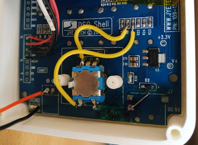
The gist of it is to bend the pins the OTHER way and to add extensions if needed.
A picture is simpler than explaining it :


I hope you're still available for comments. I too put the encoder on the wrong way. You picture above, do the four pins above the encoder play no part in the circuit and does it definitely work with just the two yellow wires attached to it? This seems to be a very simple fix to the problem!
ReplyDelete
ReplyDeletei dont remember it very well, but i think i used the wires because i damaged the pads and couldnt solder the rotary encoder to them
The tracks/pads on the DSO150 PCB are very thin and you rip them out very easily
If your pads are still ok, you dont even have to put the wires, just solder the rotary encoder
and dont use the 4 pins connector at all
double check though, i'm not 100% sure, especially that rotary encoder central pin and bottom right are connected to ground
you should have still a link with the not used 4 pins connector (from left to right)
R/L/OK/Ground
The rotary encoder from above when mounted in reverse
L GND R
OK GND
Thank you for the help. However I tried to solder wires to R6 and R7 and managed to destroy the pad on R6. I was wondering if you found the schematic the schematic anywhere on the internet so that I could replace the pad resistors r6 and r7 with proper resistors and somehow save the day?
Deletehttps://gr33nonline.files.wordpress.com/2019/06/dso-150_schematic_shell.pdf
ReplyDeleteI believe I connected R6 and R7 correctly through 1K resistors to DB1 and DB3 as per the schematic but the encoder didn't work. It occurs to me that R5 should also be connected through a 1K resistor to DB0, what do you think? This represents number 1 on your diagram and looks like the right hand connection of the top three on the encoder.
ReplyDeleteif you look at the rotary from the top, you should see
ReplyDeleteLeft-myPin2- R5 GND Right-myPin1- R6
Press- myPin3 - R7 GND
For myPin1/2/3 you should have :
- a resistance of 10k to VCC (R24/R23/R25)
- a 1k resistance to PB1/PB0/PB3
make extra sure that the 2 GND pins are really connected to ground !