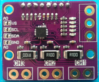
Fixing the INA3221
It 's not too complicated to change the board we have seen previously.
You 'll need to cut some tracks, i did it with a dremel and i'm not very handy, so you'll do better.
Red =Cut tracks
Blue = Add wire
1- You'll need to separate the bottom connector from the ground, cut the 3 connectors BOTH SIDES.
2- Remove the small red area below the middle resistor to isolate each channels from each other
Last, connect right side of each connector to the now isolated pad.
Mine looks like this after the operation (ugly i know):
Be wary of the small track on the left connector that leads to the left side of channel3 resistor.
I cut it while isolating the right pad.
Now it works, we can go back to the charger.


Oh hello there, same MeanX from Youtube? Wanna grab one of these module to build a 3 ch power meter, seems like your top pic is missing a cut to POW?
ReplyDeleteIndeed
ReplyDeleteYou can see the nice dremel cut on the left pad