Posts

Showing posts with the label DSO150

pyDSO: Very simple python app to control your DSO150 and to take snapshot

Image
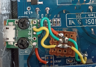
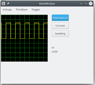
  I finally went back to this topic. Summary: The main idea is to use a usb CDC/ACM link (~ serial) to control the DSO1505 from your PC.  Of course, you'll need to connect a micro usb header to the D+/D- pins on the DSO150.  It is easy to do, the D+/D- spots are neatly marked on the PCB /!\ if a USB cable is plugged, you may be grounding the DSO , be careful. /!\ The FNIRSI style boards are using these pins to detect the AC/DC setting, you CANNOT use USB on the FNIRSI style boards. The end result looks like this : The app is very basic. It offers simple control (voltage range/time base/trigger) and more importantly the ability to retrieve nice screenshots from the DSO without using you phone (it creates output.png). The snapshots are like this : The code to run is   python_usb_control/graphical_py_app/pyDSO.py You'll need pyQt5+pySerial installed. Under the hood, a very simple protobuf-based RPC is being used, so that it is relatively portable to any langua...

lnDSO150 : Release 2.2

Image
Binaries available for Jyetech, GD32F303 and FNIRSI  https://github.com/mean00/lnDSO150 Be sure to check the wiki to know how to flash

CH32F103/FNIRSI: Success!

Image
 Still some minor tweaks to apply, but it works 

CH32F103/DSO150/FINRSI coupling selection difference

 There is another difference with the original DSO : CPLSEL pin With the original DSO, the CPLSEL (PA5) is an analog pin which gives the info about the selected coupling. When reading it with the ADC, you get : -   0 => GND -  ~ 2024=> DC -  4095 => AC (not necessarily the right values, but the principle stands). The FINRSI clone is different. It uses the CPLSEL pin *AND * another pin the "KEY" pin (PB12). That pin  was used a long time ago but is no longer needed as the threshold detection is done using the ADC watchdog Both CPLSEL and KEY are pull up GND:    CPLSEL=1   KEY=1 AC:    CPLSEL= 1    KEY= 0 DC   CPLSEL=0   Key=1 So it wastes one pin, but makes the reading much much more simple. NB: The CH32 only has one ADC, that may explain.

lnDSO150 : DFU ready for STM32F103 and GD32F303

Software is ready and works fine if you have 128 kB of flash or more. Sofwtare update over usb at last ! A lnDSO150 release will be coming soon, as soon as the CH32 chip works.

CH32F103 based DSO150 (FNIRSI clone)

 So i finally bought one to make sure lnDSO150 does run on it. First feedback : - As expected the main diff is the chip is a CH32F103 instead of a STM32F103. I added support for the CH32F103 on the blackmagic probe, so it should not be an issue to reprogram it. - The main board seems almost identical to the original one. R12 and R13 are missing which might indicate the buttons are not wired the exact same way, which would explain the problem report about pressing "OK" not working. - Some components are missing , mostly the trigger comparator stuff which is a leftover of older software. - The analog board is similar but more compact and using 100% SMD components. The FNIRSI software is not bad, looks pretty, very close to the original one in look & feel. But it feels a bit slow, we'll see how lnDSO150 performs on the CH32F103 More on that soon. Edit : Indeed, the "OK" and "Trigger" button are connected to PA11 / PA12 instead of PB6/PB7 Edit 2: There...

lnDSO150 : DFU ready soon

Image
Updating the DSO150 is a bit of a pain. Normally you can either : - Bridge a JP solder point on the board and use serial - Use the SWD interface if you soldered the pins That's a bit of a pain, and not user friendly at all. On the other hand i have now all the needed pieces to go DFU : - simple HW mode to get USB interface on the DSO150 - USB through tinyUSB to get DFU-runtime - DFU mode through a modified stm32-dfu-bootloader. This modified version adds some stuff , like a hash of the firmware to make sure it is un-damaged /complete. and it works ! The only candidate excluded is the so called "small footprint" version for DSO150 clones with CH32F103 (very experimental) which has only 64 kB of flash. The only piece left is to put a tiny LCD driver to display the USB logo when the unit goes to dfu mode and it's all good (i have ~ 4kB left, which is plenty :) ). The USB connection with the usual craftmanship :

Pre Release : lnDSO150 alpha

Image
Time to start playing with the new DSO150 firmware: lnDSO150 v2 alpha Be careful of the following : * If you dont have the rotary encoder mod, the rotary encode will not work * If you upgrade from a stock firmware, make sure the watchdog is disabled  * Sometimes,  storing the calibration values will fail. Just retry, it will work * Trigger on both edge does not really work The source code can be compiled to work the same way on STM32F103, GD32F303 and GD32VF103 Github page

lnDSO: float, arm, riscv, wait states

This is an updated version of a previously dealt with topic.  Internally, lnDso is using float to represent voltage. One could argue that it's useless and you can do int->int as the final results are pixel coordinates, but i like to have  the actual measurements available for later processing if need be. It means we have to do ADC value (int)=> volt(float) => pixel(int) In each case the processing is something along output=intput*ramp+offset Let's see how the different chip we can use for lnDSO are performing  (we use rvfp and qfp to have optimised software float lib) - GD32F303 /Cortex M4-FPU@72 Mhz : 7 kCycles - GD32F303 /Cortex M4-NOFPU@72 Mhz : 18 kCycles (~ emulating a cortex M3) Ok, no surprise here,the FPU helps a lot Last but not least , the original MCU on the DSO 150 :  - STM32F103 @72 Mhz : 27 kCycle Ouch. Most probably the flash wait states. - GD32VF103 /RiscV-NOFPU@108 Mhz : 40 kCycles (10 kCycles but the sysTick = cpuClock/4) Not great... /!\ ...

lnDSO: Pics of HW modification to use a GD32VF103 (RISCV)

Image
 For reference, here are the modifications to do to replace the STM32F103 (or CH32F103 on some cheap clones) by a GD32VF103 There are 2 extra modifications, unrelated to the VF103 :  * Put a schottky in reverse between r36 and ground to clamp the negative voltage. Probably not needed, but i saw -4 v when testing there. * Replace the diode on the bottom right by a P Mosfet in reverse to avoid wasting 0.6 v there (SH1B). 

lnDSO: Success with GD32VF103

Image
It works ! The first ~ working frankenstein DSO150 with a GD32VF103 RISCV core. As usual, the dumber the mistake is, the harder it is to find In  no special order : - Arm : The vector table must be 512 bytes aligned - Riscv : Dont forget to set the capture pin to ADC mode (the arm version does not care for whatever reason) - When switching the pins from LCD to button, initialize them properly All these are *DUMB* mistakes, but each time it took me a week to figure out why it didnt work.

lnDSO : Slow progress

Image
lnDSO is the successor to DSO-arduino STM32, i.e. alternative firmware for the DSO 150 The main differences are : - It is written using lnArduino, so much more consistent in terms of drivers / low level, compatible with STM32F1/GD32F1/GD32F3/GD32VF103 (yes, i like gigadevice chips). - Capture engine is much better, it should not lose any capture - Much simpler code base, much easier to modify The status so far is:  - it is beginning to work really  nicely on the GD32F303  (my default setup) - untested on STM32F103 but should work easily, the GD32F303 is a enhanced version of GD32F103 which is an enhanced version of STM32F103 imho. - kind of working on the VF103 (RiscV), see image below. It does not capture much :( On the VF103, working around the fact that PB3 is used by jtag  is really a pain. On the DSO 150, PB3 is used on the parrallel bus to the screen but also as the rotary encoder press detection.  The screen is finally working fine with the buttons, the r...

Replacement screen for DSO150 aliexpress link

 I broke (again) the screen on my  DSO 150 That model on ali express is a perfect replacement :  AliExpress Select ILI9341 - 8 bits ! It is not a sponsored link, just information. (The ST7789 8 bits may work also, depends on the firmware you use)

DSO150/RiscV: Blaming the innocent

Image
While redoing the DSO150 on top of lnArduino i'm cleaning up a lot of stuff i just used  "as-is" previously. In particular, i rewrote the ILI9341 driver to be fast while still being portable to some extend. NB: It's a 8 bits parallel ILI9341 , not your vanilla SPI connected ILI9341. The new code worked fine on the GD32F303  (Arm) based unit but i ran into problems when used on the risc-v powered board (GD32VF103). Same DSO board, the two mcus have the  same hw components internally, just the core is different . I had strong doubt about the "lazy" write of the riscV chip.  If that happens, it means that when you write something, it is actually written a bit later. That's problematic when you are driving LCD signals. Adding fence/fence.i everywhere seemed to fix the obvious problem. But wait a sec,  adding  plain nops works also. So either delayed write issue or timing issue. Ok, we'll add the fence/nop and look into that later. Ah, the screen goes bla...

DSO150+GD32VF103: Jtag strikes again

Image
 So after doing the small resistor removals, short, wiring  etc... we have now PB8 used in place of PB3  and PB3 is left unusued for the Jtag. The screen driver replaces on the fly  bit 3 by bit 8 when writing on the PB port.  After looking into it, it does not need to be optimised, as the code is using one or two colors at a time only. So the conversion is done once at the beginning of a sequence.  The speed loss is really small compared to vanilla code (like 0.5% slower). At worst we can compute a lookup table and lose 1kB of flash. Not worth it. Nice, let's display something and for ask the chip ID..... complete failure. And sometimes, i get a warning from openocd it has lost contact with the target. Bummer.  I  looked at my code, it looked completely correct.  I checked all the involved pins for bad soldering, all checked out ok. It took me a while to figure that one out (1 full day). It's the openocd message that gave me a hint.  Th...

DSO150 + longan nano chip / GD32VF103 ?

Image
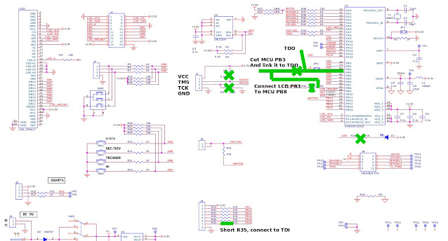
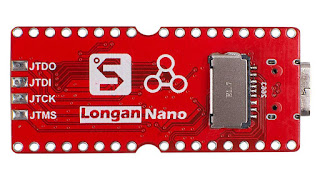
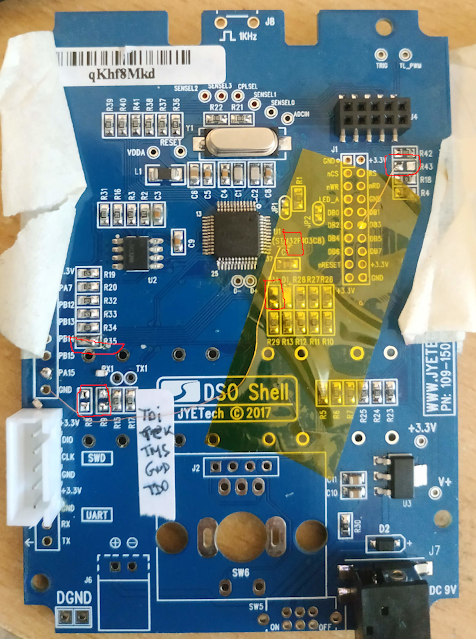
 After upgrading a DSO shell with a GD303, let's upgrade one with a G32VF103 Why ? Why not. that chip is fast and has a FPU like the gd32f303. Additionnaly, it will be a good test bed for lnArduino, that works indifferently on those. While the GD32VF103 is more or less pin to pin compatible with the GD32F1 or STM32F1, there is one big difference : Arm chips are using SWD while the VF is using jtag.  We need 2 more pins : TDI (PA15) and TDO (PB3) On the DSO150, PA15 is used for the small red led. We dont need that. PB3 is more of a problem, it is used in the parallel display bus. So we'll have to use another B port pin and do on-the-fly bit swap. We'll use PB8, used for PWM comparator that is not used anyway. Let's go for the change : * Remove R8/R9: They are pull up/down resistors for SWD. No SWD, not needed. * Remove R14 to free up PA15 * Remove R43 to free up PB8 * Short circuit R35 to have a direct TDI signal to the MCU * Cut PB3 right next to the MCU and connect the...

DSO150: and even more fun with usb

Image
 There is now a very basic python/qt5 app in the pyDSO folder enabling you to do simple control & capture grab of the DSO 150 It *is* slow but kinda works

DSO150, more fun with USB

Image
Recap :  If you did the usb mod on the DSO150 and use the latest head version of  https://github.com/mean00/DSO_STM32Duino , you can control the DSO150 over the usb link. The pyUsb folder contains several python script to change voltage, timebase etc... Color! One of them (  pySerial_draw.py), enables you to retrieve the current buffer , display it in a window and save the end result as a png. You'll need python3 and python3-opencv2. That script is very small (~ 40 lines) and is just a proof of concept/demo. The end result looks like that: Just a small warning  If you overclock the STM32 you'll probably not have a working usb connection.

DSO150, fun with USB

Image
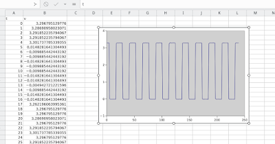
 I've postponed that from a long time, but finally... Let's assume that you did the USB mode, and run that small python program from DSO150 import DSO150 import csv import time dso=DSO150() print("Asking for a capture ") data=dso.GetData()   f = open('output.csv', 'w') writer = csv.writer(f) writer.writerow(['t','v']) l=len(data) for i in range(0,l):    ns=[i, float(data[i])]    print(ns)    writer.writerow(ns)   f.close()   Connect your DSO150 with my firmware, run the python script and... You end up with output.csv and when imported in your favorite spreadsheet....   Most configuration commands are available through python3/ usb (set voltage, trigger, ask for a capture....) It's very basic for the moment but can be very handy BTW i suck at python too...

DSO150 Playing with floats & speed

  My version of the DSO 150 firmware is using float internally to convert ADC to voltage. It could probably be faster using 32 bits fixed point, but float is good enough for now. Let''s see how it evolves, the basic test is converting 240 samples from ADC to voltage For each sample the formula is OUT=IN*multiplier - Offset STM32F103 overclocked to 128 Mhz "Old code" : 880 us "Newer code" afer optimization : 440 us Using fast float lib (qfp) : 380 us So twice as fast, not bad GD32F303 at 96 Mhz It is a cortex M4 core with FPU "Newer code" without FPU : 350 us "Newer code" with FPU : 83 us