Let's make a ESR meter : Principle (part 2)
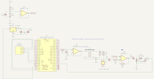
Overview The complete schematic is as follows It it made of 4 parts : Sinusoidal signal generation Resistance divider (impedance actually) Amplification Peak detection Sine generation The sine is generated using a timer controlled dma feeding the PWM to have a sine envelop on a high frequency signal (see previous post). A simple low pass filter will only keep the sine signal and it then goes through the transformer. That transformer has been salvaged from an old phone charger. It has a 1:20 ratio. So the input signal is ~ 3.3 v peak to peak with ~ 100mA max current, the output is 165 mv peak-to-peak BUT have a 2A max current. Since the voltage is so low, that helps for in-circuit measurement, the voltage is not enough to trigger a diode/ NP junction or most mosfets. Resistance Divider / Amplification / peak detection The output of the divider is Z/(R9+Z) x VccTransfromer Z is the total impedance of the capacitor at ~ 50 khz. It is assumed the cap is high enough s...