Let's make a ESR meter : Principle (part 2)
Overview
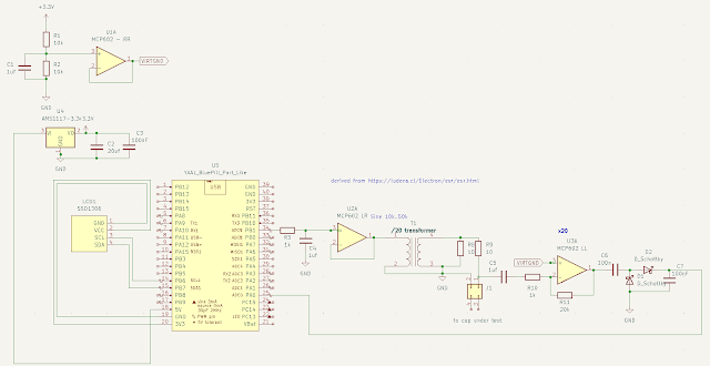
The complete schematic is as follows
It it made of 4 parts :
- Sinusoidal signal generation
- Resistance divider (impedance actually)
- Amplification
- Peak detection
Sine generation
The sine is generated using a timer controlled dma feeding the PWM to have a sine envelop on a high frequency signal (see previous post).
A simple low pass filter will only keep the sine signal and it then goes through the transformer.
That transformer has been salvaged from an old phone charger.
It has a 1:20 ratio. So the input signal is ~ 3.3 v peak to peak with ~ 100mA max current, the output is 165 mv peak-to-peak BUT have a 2A max current.
Since the voltage is so low, that helps for in-circuit measurement, the voltage is not enough to trigger a diode/ NP junction or most mosfets.
Resistance Divider / Amplification / peak detection
The output of the divider is Z/(R9+Z) x VccTransfromer
Z is the total impedance of the capacitor at ~ 50 khz.
It is assumed the cap is high enough so that the ESR part is much bigger than the capacitance at that frequency. That means a capacitor of some uFarad at least.
The output is then multipled by 21 and a simple peak detector is used to get the peak value (most of it)
and it is then fed to an ADC entry of the MCU.
Now the fun part begins, how do we get the ESR from the value read by the ADC ?
(not as simple as it seems)


Comments
Post a Comment