Posts

Showing posts from February, 2019

DSO 150: Timebase

The voltage management was designed by Jyetech to reflect the values they wanted to use. The resistors have the right values to form good voltage dividers, and as a result, converting between them and volt/div is pretty simple. It's not so simple for the timebase. Ideally, we'd like standard value, such as 10us/div, 50ms/div etc... Since we use 24 pixels per div, that would mean 10us/24, 50ms/24 etc... sampling frequency Unfortunately, we don't have the required  flexibility as far as sampling frequencies are concerned. Here is a  table of all the available values (prescaler x sampling time) 2 4 6 8 1,5 0,39 0,78 1,17 1,56 7,5 0,56 1,11 1,67 2,22 13,5 0,72 1,44 2,17 2,89 28,5 1,14 2,28 3,42 4,56 41,5 1,50 3,00 4,50 6,00 55,5 1,89 3,78 5,67 7,56 71,5 2,33 4,67 7,00 9,33 239,5 7,00 14,00 21,00 28,00 Time/sample (us) Multiple by 24, to get the time/div Not so great in terms of user exper
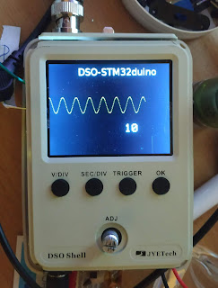
DSO Shell : High quality waveform display

I tried several methods to redraw the waveforms as fast as possible, while keeping a high quality display. The target is ~ 30 fps, crystal clear. The underlying method is that we only draw vertical lines, not random lines. That way we maximize the setAddrWindow/push colors mode of the display controller. Method 1: That method is the dumbest: we clear the area to paint and redraw everything needed. Pros It is actually very fast, because the amount of data to paint is small compared to the display. Something like 5 to 10% Clearing an area with black is fast, just put 0 on the bus and toggle the write pin as much as needed. The speed is ~ ok (14ms) Cons It flickers a lot. It flickers because we actually draw the screen twice : once in black, once with the waveform. Method 2: Draw once To avoid the aforementioned flicker, the idea is to pre-calculate a column and send it. Pros It does not flicker at all (we only draw once). Cons  it is kind of slo

DSO 150 Houston we have lift off

Image
Very basic DMA-ADC capture test case with code derived from PigOScope  and signal coming from my El Cheapo signal generator . That's a promising start.

DSO150- Input gain

Image
The DSO 150  input gain  is a 4 stages  circuit : G1 is driven by SENSEL3 (aka PA14) and enables switching between a gain of 10/11 (SENSEL3=1) and 10/1100 (SENSEL3=0) G2 gain is 2 G3 gain is driven by SENSEL0/1/2 (PA11/12/13) and can go from /1 to /40, more on that later G4 gain is (1+1000/150)=~ 7.7, additionally the signal is shifted by 1000/680 volt = 1.47 v The overall gain can vary from 10/11*2*1*7.7 => ~ x14 to 10/1100*2/40*7.7 => ~ /285  The SENSEL0..2 order is a bit weird : Gain       SENSEL0..2 GND           1 /1                4 /2                6 /4                7 /10              0 /20              5 /40              3 Ultimately the gain follows this table : SENSEL0..3                Gain 0                                    /71 1                                    GND 2                                    NC 3                                    /286 4                                    /7 5