esp32C3: Using embedded jtag/usb to debug
This is a follow up to the ESP32C3 jtag setup
The idea here is to detail the missing pieces in the documentation to use the embedded jtag/usb converter.
I'll be a bit heavy handed in removing stuff, it may not be 100% necessary. Your mileage may vary.
Jtag setup
The esp32c3 has regular jtag pins connected to GPIO 4/5/6/7
It also has a internal usb jtag+CDC/ACM connected to pins GPIO 18 & 19.
By default it's using the usb/jtag one
EFuse
There is a efuse to automatically switch from internal jtag/usb to external jtag depending on the GPIO10 state at boot up
It does not work, there is an bug entry.
If you enable that bit (JTAG_SEL) it will use external jtag, period, never internal usb/jtag.
Ifever you modified it, like i did, you can recover usb/jtag by setting the disable pad jtag efuse, and it will be locked on usb/jtag forever.
In short, use USB/jtag only and dont play with the efuses.
Leds everywhere
On the devkit or similar boards from alibaba the jtag pins are also used for something else.
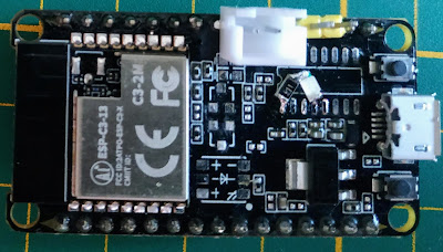
GPIO18/19 are connected to power Leds (small yellow and bright white)
GPIO 4/5/6 are also connected to the "RGB" led
I dont need those, i dont want the signals to be changed, so i removed *all* the leds.
As a bonus that frees GPIO 4/5/6
I added directly a small SMD led over 3.3v / GND with a 500 ohm resistor (see picture below)
/dev/ttyACM0
So now we have jtag working (it does !) and a serial link appears (/dev/ttyACMx on linux)
If you are using recent/github esptool and esp-idf you can use that serial link to download code and potentially get logs & stuff (did not try the log part, only the download part)
As a result, i also removed the CH340 chip. Dont need it.
So as of now, my setup is :
* Use usb/jtag to debug
* Use CDC/ACM to download code
* Use directly the uart rx/tx pins to get logs (you'll need a serial/usb converted of some sort)
It means my debug setup only consumes 4 pins (Gpio18/19 + uart RX/TX)
/!\ The location of the pins varies depending on the board
The 2 yellow pins are RX/TX
The 2 pins in the white JST connector are connected to USB D+/D-
Connect the usb connector to the JST connector, THEN power up the board
And now openocd-esp32 native connects to the riscV core.
openocd -f board/esp32c3-builtin.cfg
Open On-Chip Debugger v0.10.0-esp32-20210902-1-gca6a6332-dirty (2021-09-29-19:48)
Licensed under GNU GPL v2
For bug reports, read
http://openocd.org/doc/doxygen/bugs.html
Info : only one transport option; autoselect 'jtag'
Warn : Transport "jtag" was already selected
Info : Listening on port 6666 for tcl connections
Info : Listening on port 4444 for telnet connections
Info : esp_usb_jtag: Device found. Base speed 40000KHz, div range 1 to 255
Info : clock speed 40000 kHz
Info : JTAG tap: esp32c3.cpu tap/device found: 0x00005c25 (mfg: 0x612 (Espressif Systems), part: 0x0005, ver: 0x0)
Info : datacount=2 progbufsize=16
Info : Examined RISC-V core; found 1 harts
Info : hart 0: XLEN=32, misa=0x40101104
Info : Listening on port 3333 for gdb connections


Comments
Post a Comment