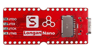
Longan Nano : Making a simple signal generator
 The Goal here is to make a simple signal generator with the longan nano. We'll just add a rotary encoder and that's it.
DAC
It seems the pins used are hardwired and cannot be changed.
That could be a problem as they are shared with 2 SPI0 signals, connected to the screen.
The DAC will do a conversion each time a trigger event happens.
That event can either be software (i.e. you write a register) or a timer.
A DMA can be scheduled using said timer too.
What does it mean for us ?
It means we prepare the data to send, a sine wave for example in a buffer, setup a DMA transfer and program the timer so that a new sample is sent to the DAC at the proper time.
Each time the timer rolls over, the DMA will send the next sample to the DAC. It's not exactly clear how fast the DAC can go.
For a sine, we'd like to have ~ 100 points or so to have a clean curve.
Round up/round down issues
The clock frequency is 108 Mhz/(car*psc), where psc is the timer prescaler and car is the timer reload value.
it means we cannot create exactly all the timer frequency we need.
For example, say we want 150 Khz and 100 samples, the exact divider is 7.2
Let's say we take 7, that gives a real frequency of 154 khz
We can do better by reconstructing the waveform using the timer value we use, i.e. adjusting the # of samples to minimize the error.
In the above example, it means we'll not use 100 points but 103
We still have an error but it's now small-ish and we can compute it : 149.8 kHz
Not perfect but not too bad. We can go up to ~ 120 kHz.


Comments
Post a Comment